...
...
...
...
...
...
...
...
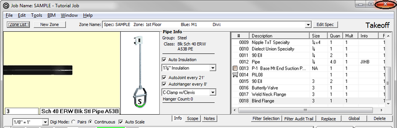
Now that you are beginning to understand how the digitizer functions for taking off pipe, you are ready to begin taking off the Tutorial drawing. This exercise, Exercise #3, gives you an opportunity to use the most common items defined in a spec: Pipe, Fittings, Valves, Hangers, Flanges, Specialties, and Assemblies.
The Takeoff Screen is customized using the Spec for that Zone. Notice that the title of the Spec and Zone are in the upper left hand corner of the screen.
In Exercise #1, you practiced different ways to take off pipe; therefore, we are going to give you a great deal of flexibility on the tutorial takeoff. We will ask you to take off a run of pipe and it’s up to you to decide how you want to take it off.
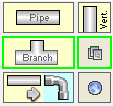
- Select the button next to Continuous. You will take off pipe in the Continuous mode for the tutorial.
- Select the size of 6″.
- Select Pipe.
- Click on touchpoints 1, 3, 4, and select Accept. (Skip touchpoint 2 because it wasn’t a break in the pipe run. If you touched it, the system would give you an incorrect count of joints.)
- The system size is still 6″ so click 90 Elbow (which is touchpoint 3) and select Accept.
- Select Reducing Tee. A pick list appears.
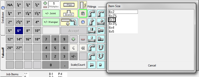
- Select 6×3. (You can do this by selecting 6×3 with the mouse cursor or click 3 on the digitizer template.)
- Click Accept on the digitizer template or touch the pen down on touchpoint 4 (which is the Reducing Tee on the blueprint). Press the Accept button on the touchpen.
- Select a Reducer (the box next to the tee). This works the same way as the Reducing Tee.
- Select 6×4.
- Click Accept or click on touchpoint 4 (which is the Reducer on the blueprint). You are done with 6″ and now you need to move to 4″ size.
- Move your pen to the 4″ and click down. Click on Pipe and click on 4, 5, and 6. Select Accept.
- We have a 4 foot vertical drop so click on Vertical Pipe. (Select vertical pipe any time you don’t want the system to generate hangers.)
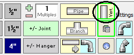
- Click on the 4 and select Accept.
- Click on 90 Elbow then touch points 5 and 6.
- Select Accept with the pen button or touch Accept on the touchmenu.
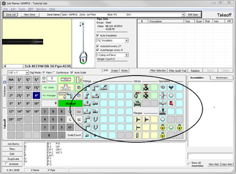
- Now take off the branch lines.
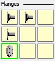
- Now you need a branch outlet. Branch outlets are located under the specialties palette.
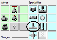
- Click ¾”, then click thread-o-let. You will get a list of available sizes.
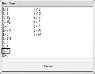
- Branch size shows first and pipe size is second. Select ¾x6. Select Accept.
- Next, you need a ¾ nipple located directly above the thread-o-let. Click on the nipple. Select ¾x4. Select Accept. This is touchpoint 2.
Now you need a Dielectric Union.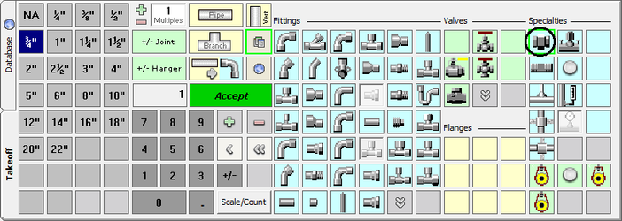
- Select Dielectric Union and touch point 2 once. Select Accept with the pen or on the template.
- Select 90 Elbow and touch points 2 and 7. Select Accept.
- Click Pipe Branch and touch points 2, 7, 8, and 9.
You need the P-1 Job Item which you will see on the bottom of the screen.
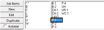
- Select P-1 and Accept.
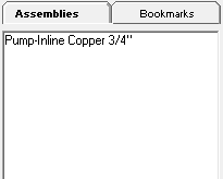
The detail of the pump requires quite a few fittings and specialty items. Instead of taking off each item individually, select an assembly. - Select PIL08-Pump Inline Copper ¾ assembly.
You will see a picture of the items in the “Assembly picture”.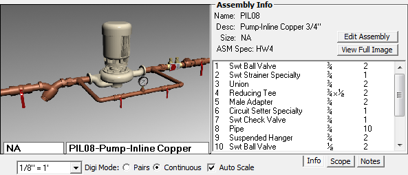
- Select Accept.
You have one last branch to take off.
- Change size to 3″. Select 90 Elbow and touch points 4 and 10.
- Select Pipe Branch. Touch points 4, 10, and 11.
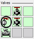
- You need a 3″ Butterfly valve. Click Butterfly Valve and select Accept.
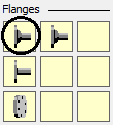
- Next you need a 3″ flange located on the Flange Palette.
When you click on the flange, notice the system is showing you that you are getting the gaskets and nuts and bolts as part of this flange.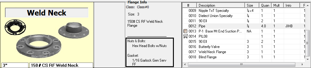
- Select Accept.
- Click on the Blind Flange and select Accept.
In addition to the items listed in the Takeoff list, other items are being generating automatically based upon the settings in the specification. When Pipe was being taken off, the following screen appeared showing you how often joints and hangers were being calculated.
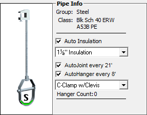
In the Takeoff list, look at the J following the pipe taken off. This indicates that AutoJoint is operable and the appropriate joints were taken off with this length of pipe. Also look at the H following the pipe taken off. This indicates that AutoHanger (or AutoExcavation) is operable and the appropriate hangers components are being taken off with each length of pipe.
You are now done with Takeoff. Click the Close button.