To open any link in a new tab, preserving your position in the current article, just hold down the <CTRL> key on your keyboard before clicking the link or click using your mouse wheel.
Using the EarthWork Pro v3 Plugin -
** Read this first ** This plugin requires the images to be in TIF format. Earthwork Pro cannot calculate volumes when performing takeoff on PDF pages. PDF pages must be converted to TIF images before you digitize contours or spot elevations.
Contents
Complete Your Takeoff
Trench Tools
You will have Trench Tools that can display takeoff values by Linear or Volume measurements. This is the main form you will see when you launch the Trench Tool. Trench slope options can be selected from the main form.
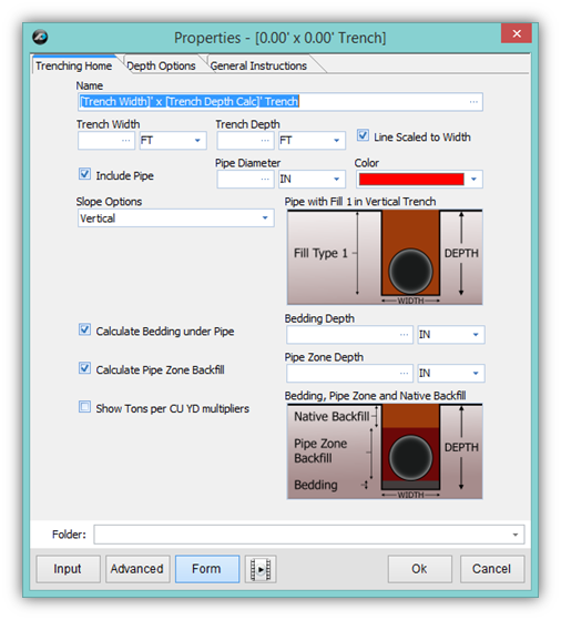
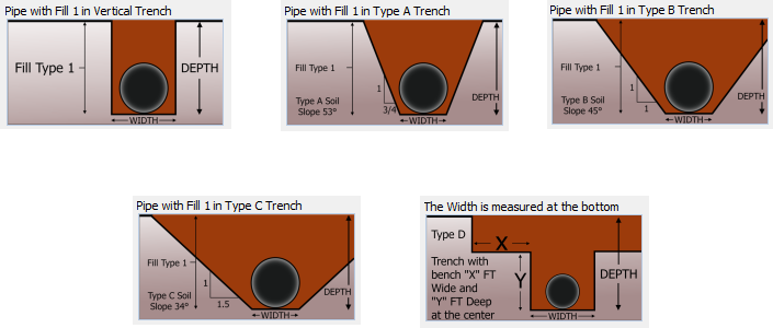
There are five total trench slope options.
Vertical Trench (Fig. 9)
Type A Trench (Fig. 10)
Type B Trench (Fig. 11)
Type C Trench (Fig. 12)
Type D Trench (trench with bench) (Fig. 13)
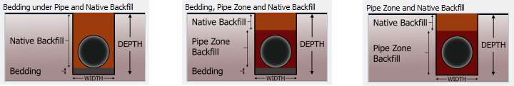
The Trench Tool also has several options for backfill. (Figures 14, 15, 16)
All of the Trench Tool features will be outlined in greater detail later on in this guide.
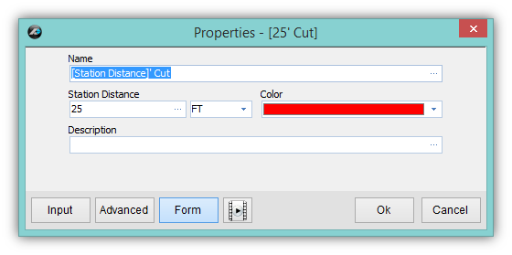
Sectional Cut & Fill
Sectional Cut and Fill tools are also included with this plugin and will be discussed further in this guide.
Truck Parts and more…
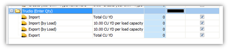
Truck Parts are a new addition to version 3.0. Trucks allow you to calculate Import and Export totals in either CU YD or by the load. (Figure 18)
The rest of this guide will cover all other features, parts and assemblies of Earthwork Pro V3 in more detail.
Digitizing Spot Elevations
Choosing Existing or Proposed
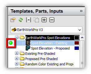
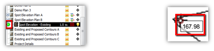
From the right hand window for Templates, you select the folder labeled EarthWorkPro Spot Elevations. In the folder you have a template for Existing and Proposed Elevations. To launch the template either double click on it or use the Green button to the left. (Figure 19)
Default Properties
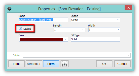
The form on the right shows the default settings. You can uncheck the box next to “Scaled” if you prefer it. Unchecking the box will make it easier to see the points you digitize on the page.
Note: You can also change the properties later on after you do the digitizing.
Setting the Point and Entering the Elevation
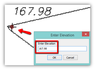
After clicking “Ok” on the form in Figure 20 you begin by clicking any of the points on the page. After the first point is clicked you will enter the elevation and continue to the next point. Repeat the process until you have digitized all the points within the Area of Interest. (Figure 21)
Note: Area of Interest is the area, defined by the user, which will be analyzed for Cut and Fill calculations. It is not required to digitize all of the points on a page, but just the points that will define the Area of Interest.
Triangulating the Points
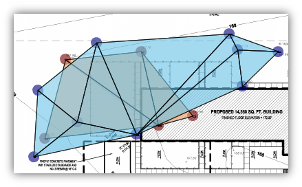
After all of the digitizing is done either for Existing Spot Elevations, Proposed Spot Elevations, or for both Existing and Proposed Spot Elevations you can click the Triangulate button on the Home Tab. PlanSwift will automatically draw areas in between all points and an average elevation is calculated from the three points it touches. Areas are shown in Blue for Proposed and Brown for Existing. (Figure 22)
Fixing Takeoff Mistakes
Entering Elevations
If you made a mistake entering an elevation, and already clicked “OK” a label will show you the elevation. To change the elevation for any particular point you MUST: First, turn off the digitizer, next delete the point by Double Clicking it and finally re-digitize the point by using the green “Continue With” button found next to the item from the left hand side. (Figure 23)
Note: Changing the label will NOT change the entered elevation for the point. (Figure 24)
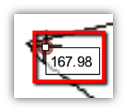
The point MUST be deleted and then re-digitized in order to enter a new elevation for it.
Digitizing Points
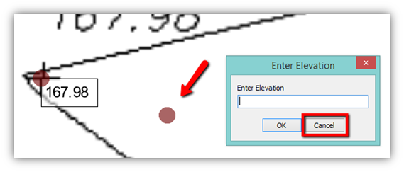
If you make a mistake and click a point where there is no spot elevation simply click the “Cancel” button on the Enter Elevation window. This will close the window and automatically delete the last point placed. To continue, proceed with clicking a new point in the correct position. (Figure 25)
Digitizing Existing & Proposed by Area
Choosing Existing or Proposed
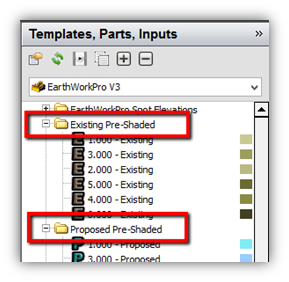
From the right hand window for Templates, you select either the folder labeled Existing Pre-Shaded or Proposed Pre-Shaded. (You can also use random colors for Existing and Proposed Contours.) There are six pre-shaded colors, brown for Existing and blue for Proposed. These templates can be re-used as many times as is necessary to complete a job. The numbers 1-6 are simply “place-holder” numbers for the pre-shaded templates. To launch the template either double click on it or use the Green button to the left. (Figure 26)
Default Properties
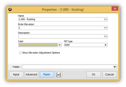
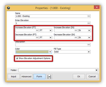
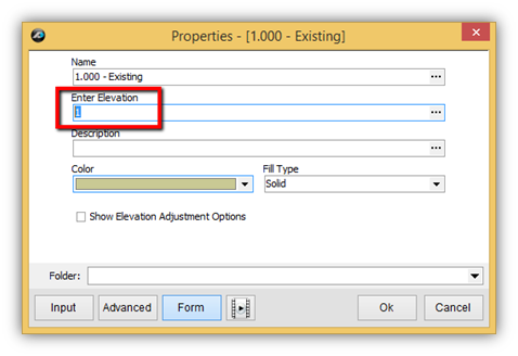
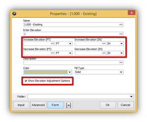
The form on the right shows the default settings. The form can also be expanded by checking the box next to Show Elevation Adjustment Options. This will add four more properties to the form that allow you to adjust the elevation that is entered. The Name property uses a formula to modify the name with the value you enter on the Enter Elevation property. You can change the Name Property, but it is not necessary or really recommended. The only thing you really need to do with this form is to enter the elevation and adjust the it if necessary. You can also add a description, but again it is optional. After entering the elevation, simply click “Ok” to begin digitizing. (Figure 27)
Note: You can always change the properties after you do the digitizing if you need to adjust the elevation later on.
Entering the Average Elevation
In Earthwork Pro we advise you to enter the average elevation between two contours. The most important property to understand and enter in on the form is the “Enter Elevation” property. For Existing Pre-Shaded and Proposed Pre-Shaded templates there is a number 1-6 already filled in on the property. (Figure 28) This is a simply a “placeholder value” that is designated to the pre-shaded color for that particular template. (These pre-shaded templates can be reused as many times as needed) You will highlight the “Enter Elevation” property and proceed to enter the average elevation between to two contour lines that you will be digitizing.
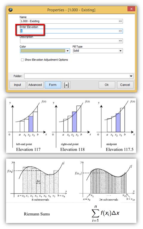
For example, if you have contours of 117 and 118 you will enter 117.5 for the value of the elevation between those contours. (Figure 29) The value of 117.5 will be averaged throughout the entire area that will be digitized. Hypothetically, if you were to go to the site and walk anywhere within the area between those contours of 117 and 118 you would be, plus or minus 0.5 at most, standing at an elevation of 117.5 at any given point within that area. It is very important to understand that topography lines and contours are only a very close approximation of how the earth is curved. Earthwork Pro was developed using the fundamental basic principles that are used to approximate the area under the curve in math. The area under the curve has also been sequenced using Riemann Sums and generates even better approximations with more subintervals. These basic principles are what guide us to enter the AVERAGE elevation between the two contours for the Earthwork Pro plugin.
(Figures 28, 29, 30)
Digitizing the Area Between the Contour Lines
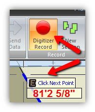
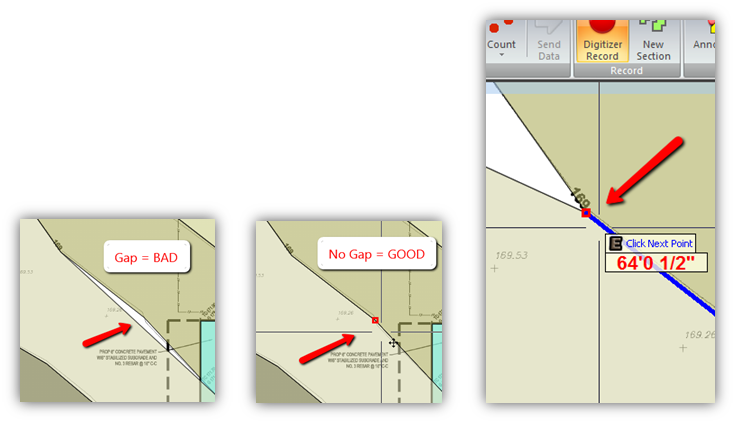
After you have entered the elevation and made any necessary adjustments, click Ok on the form. (Figure 28) The “Digitizer Record” button on the ribbon bar will light up RED indicating that the digitizer is in record mode and you will also see the Flying Tool Hint prompting you to “Click Next Point” (Figure 31)
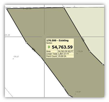
Next, you will click points following along the contour line on one side. When you reach the limit of the Area of Interest you will cross over to the other contour line and finish out defining the area between the two contour lines.
(Figure 33)
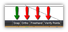
Note: Turn off the ORTHO, FREEHAND, and VERIFY POINTS buttons found at the bottom of PlanSwift. Use the SNAP button during the digitizing of all the contours. TIP: You can toggle the SNAP using the F3 key on the keyboard.
(Figure 32)
Modifying the Default Snap Settings
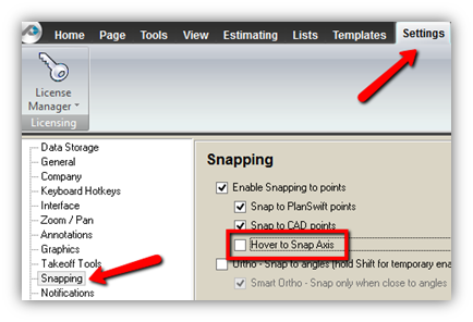
PlanSwift has a setting called Hover to Snap Axis that you can turned on in Settings. This is used for framing and is not needed for Earthwork Pro takeoffs. To turn this off, open the Settings Tab on scroll to the Snapping options. Simply uncheck the box next to Hover to Snap Axis.
Using the Snap Feature for Digitizing
The Snap feature makes it easy to digitize along a contour line that has been previously done. You can toggle it on and off using the F3 key. You will see a RED box when you hover over a previously digitized point. This is important because you don’t want to have any gaps in the coverage of the areas you are creating for existing and proposed contours. Not only are gaps bad, but any overlapping areas are bad too. Make sure you use the Snap feature to eliminate any potential gaps or overlaps. (Figures 35, 36, 37)
Adding Points to the Area to Close the Gap
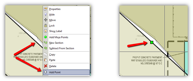
Sometimes you will realize you have a gap long after you have finished digitizing an area. (Figure 35) You can add points to the perimeter of area to easily close the gap. You add points in two main ways. You can Right Click and choose Add Point from the menu OR you can simply Double Click on the black dashed line that outlines the area. Left Clicking on the new point will make the point turn GREEN. Then move the point by Left Clicking and dragging it to where it needs to be to close the gap. (Figures 38, 39, 36)
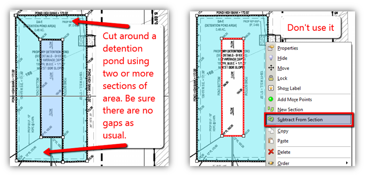
Cutting Around Topography Instead of Using Subtract From Section
PlanSwift has a feature to subtract from a section, however for the Earthwork Pro templates this feature cannot be used. It will mess up the calculations. Instead, you will need to cut around certain topography instead of cutting it out. If you used the Subtract From Section option from the right click menu you see the subtracted portion highlighted in RED. This is bad and cannot be used. DO NOT use the Subtract From Section option. If you did use it, you will need to re-digitize those areas using the cut around technique shown in the image on the left. (Figures 40, 41)
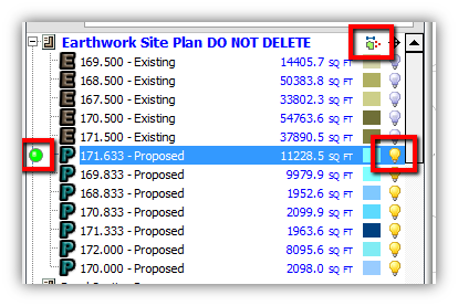
Useful Tools for Digitized Items – Hide or Show and Continue With
During the process of digitizing all of the existing and proposed contours there will be lots of items listed on the left hand side of PlanSwift in the Pages window. You can hide or show items using the YELLOW lightbulb buttons. You can also turn on or off ALL of the digitized items using the tiny toggle button to the right of the page name.
You can also use the GREEN Continue With button on the left of any item if you need to add more area for that particular contour.
(Figure 42)
Launching the EarthWork Plugin
Once all the digitizing for Existing and Proposed is complete, navigate to the Home Tab and click the Earthwork Pro V3 button from the ribbon bar...
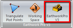
or, if your Earthworks Pro buttons are stacked...

When you click on Earthwork Pro button, Earthwork Pro V3 open a new window, and you see an orange Loading Screen...
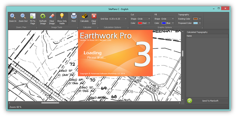
(the window shown above is used for calculating cut and fill )
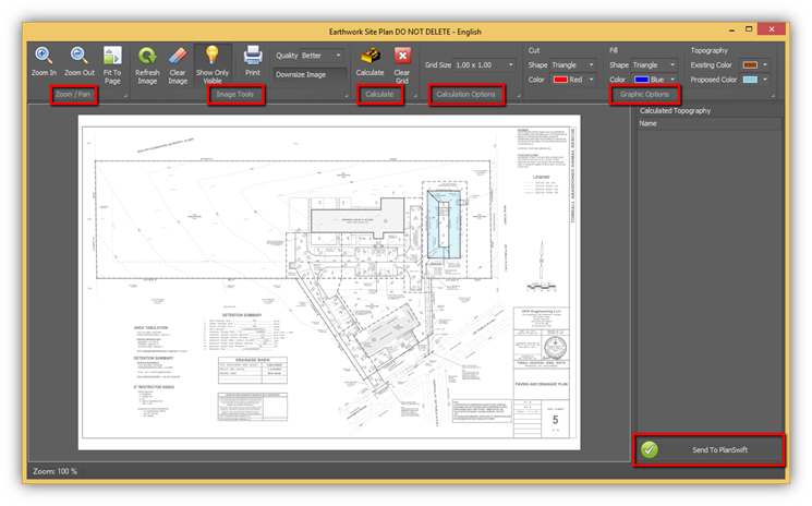
On the new window's ribbon bar there are several key Ribbon Groups:
- Zoom/Pan
- Image Tools
- Calculate
- Calculation Options
- Graphic Options
In the bottom right corner there is the “Send To PlanSwift” button. You will use this button to send the calculations back to PlanSwift after they are calculated in this window. (Figure 49)
Calculating the Topography of Existing and Proposed
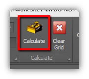
Click the Calculate button from the ribbon bar. There are several options you can change before you calculate, but generally speaking you will usually calculate without changing any of the default options. (Figure 50)
After clicking the “Calculate” button, Earthworks Pro draws in a grid of Blue and Red shapes. (The default shape is the triangle and can be changed on the ribbon bar. Also, the shape’s color can be changed on the ribbon bar)
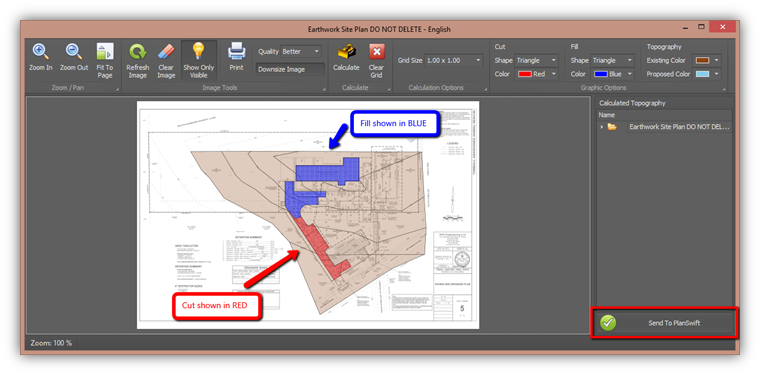
Once the topography has been calculated in this window, click the “Send to PlanSwift” button in the lower right corner to send the calculations back into the Estimating Tab of PlanSwift.
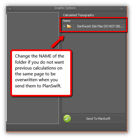
If you need to run calculations on the same page, we recommend you rename the folder in the Calculated Topography panel. Each time you click “Send to PlanSwift” (unless you have changed the Name of the folder) the previous calculations you sent to PlanSwift are overwritten by the latest calculations.
Changing the Name of the folder prevents the original calculations from being overwritten and adds a new folder to the Estimating Tab in PlanSwift.
It can take some time for the calculations to import into PlanSwift depending on how big the job is. PlanSwift confirms the calculations have been successfully exporting into the Estimating Tab of PlanSwift.
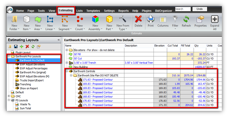
On the Estimating Tab in PlanSwift, select the Earthwork Pro Default layout from the left hand side and then expand the folders under the Earthwork Controls to see the calculations. (Figure 54)
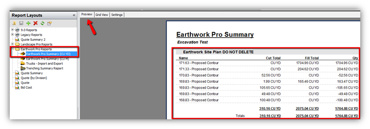
The REPORTS tab also has a report to display the calculations. Use the Preview tab to see it as so. (Figure 55)
Adjusting Elevations on Multiple Contours
Earlier, we showed in the properties window that elevations can be adjusted on a digitized contour. Elevations of Proposed contours are generally the ones being adjusted, but Existing can be adjusted too. (Figure 56)
Many times, the elevations need to be adjusted on many of the Proposed elevations. Instead of changing them all one-by-one, a four step approach is suggested to adjust the elevations.
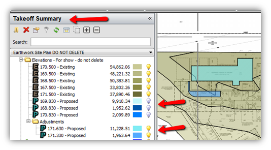
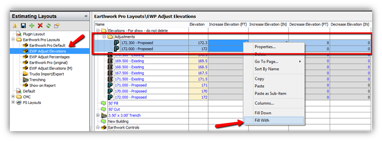
First, in the Takeoff Summary window on the left side of PlanSwift, use the lightbulbs to hide any contours you do not want to adjust. (Figure 57) Second, select the remaining contours and move them into a new folder. I labeled my new folder “Adjustments” for this example. (Figure 57) Third, click over to the Estimating Tab in PlanSwift and find those contours in the new folder you created. (Figure 58) Fourth, switch the Estimating Layout to the EWP Adjust Elevations layout, highlight all of the contours use the SHIFT key to select them, then right click in the desired column you’re are adjusting the value for and use the Fill With option to set the new value. (Figure 58)
Copyright 2023 ConstructConnect