Legacy Onscreen: 03. Tools
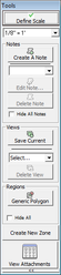
The Tools palette allows you to define the scale for the current planfile, create and manage notes, designate views (or “hot spots”) for sections of interest within a planfile and to draw a generic bounding box around a region on the planfile (called “Polygons” in OnScreen). This chapter will explain each of these operations in detail.
Define Scale
Whenever you open a new planfile in OnScreen takeoff, you will be required to define the scale. The scale value is used to calculate lengths for the runs of pipe, the placement of fittings, etc. so defining the scale correctly is an important step towards ensuring accuracy and reducing errors. Since the scale value is so important, no other operations can be performed until this step has been completed properly.


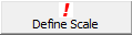
When you open a planfile for the first time, the Define Scale button will show a red exclamation mark. This is a reminder that you must define your scale before you begin. You will see the “Define Scale†banner (shown below) in the main canvas window. Clicking on the Define Scale button will load you planfile in the viewer and your cursor will change the to Scaling cursor (shown above).

Scan your planfile and locate an area with a known measurement (we recommend using a doorway). Position your cursor at the starting point, then press and hold the Right Mouse Button. With the Right Mouse Button down, drag the scaling cursor to the desired length then release the Right Mouse Button.
After releasing the Right Mouse Button, you will be presented with the Define Scale Dialog (pictured below).

Enter the length, in inches, for the span you defined, then press OK.Your scale is now defined and you may begin using QuoteSoft Pipe OnScreen.
Notes
Placing notes on a planfile is a quick and convenient way to convey important information. The notes you place on a planfile will be saved with the zone information and you will be able to view the notes every time the zone is loaded. Placing a note is also an easy way to refer back to a specific location within a planfile, as the position of a note acts as a “bookmark” for the planfile and can be used to quickly “jump” back to that location.

To add a note to your planfile, click the “Create a Note” button on the Tools palette. Your Cursor will change to the “Note Cursor”.

Move the cursor over the planfile and click the Right Mouse Button at the location where you want your note to be placed. The Notes Dialog Box will appear.
The Notes Dialog Box allows you enter the text for your new note, set the background color text size and the size of the bounding box of the note itself.
To set the color, simply click the square with the desired color from the “Bkground Color” frame.
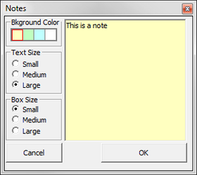
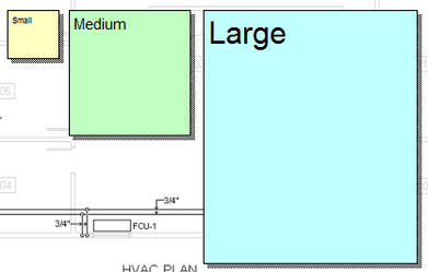
Changing the Text and Box sizes will affect how your note appears on the planfile. A large text size will be easily readable when the planfile is zoomed out completely, while a note with a small text size will be difficult to read without zooming in. The example to the left shows the results for each of the settings within a planfile that is zoomed out to 50%.
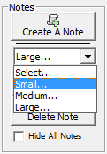
One advantage to creating a note is that it also serves as a “bookmark” for the location within the planfile where it is placed. You can jump directly to a note by selecting it from the “Select…” pulldown. The pulldown will list each note by displaying the first five characters in that note. When you select a note from the pulldown, the planfile viewer will jump directly to the note and the “Edit Note” and “Delete Note” buttons will become enabled.
To hide every note, click the “Hide All Notes” check box at the bottom of the Notes group. This will turn notes off until you uncheck the option.
Views
Navigating to specific sections within a planfile is a common task which you will perform many times while working in OnScreen. You can utilize Views to simply and quickly jump between important sections of your plan.

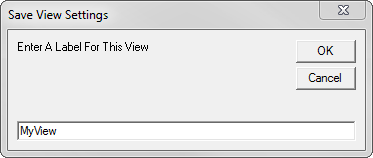
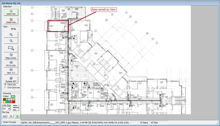
When navigating through a planfile, you can save the current location and zoom settings by clicking the “Save Current” Button.
The “Save View Settings” Dialog will appear and you will be able to enter a customized name for each view you store in this way.
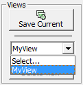
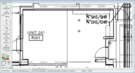
To access a saved view, simply select the named item from the pulldown in the “Views” group. Your view of the planfile will be set according to the setting in the selected view.
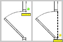
Before View Selected:
After View Selected:
Regions
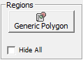
The “Draw Polygon” tool will allow you to create a generic region joined to a specific area on your planfile.
To create a Polygon region, you begin by clicking the Draw Polygon Button. The cursor will change to a cross-hair to indicate you are in Polygon mode.
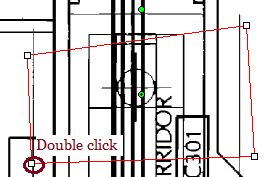
Next, place the cursor over the point where you wish to begin your region and Single-Click the mouse. Move your cursor to the next point for your shape and Single-Click again to mark each point.
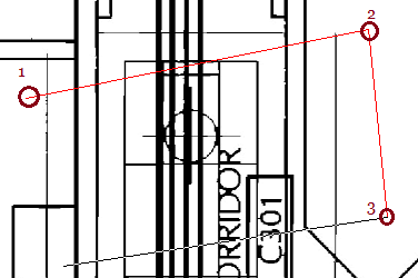
When you are finished defining the points for your region, simply Double-Click the last point and the region will automatically join up to the starting point and close the region. Once a region has been completed, you will notice that each point has turned into a square “anchor”, indicating that you can now resize and move this polygon region to any desired shape.
Polygon Regions will be stored as part of the current zone. If you are loading up a zone as a zone layer, you will see any polygon regions that were created in that zone, but they will be locked and cannot be edited. To edit a polygon region, simply load up the zone containing that region into OnScreen and you will be able to modify the Polygon Region without restriction.
©2022 ConstructConnect, Inc. All rights reserved.