...
| Table of Contents | ||
|---|---|---|
|
| Page Tree | ||
|---|---|---|
|
Complete Your Takeoff
Trench Tools
...
You can also use the GREEN Continue With button on the left of any item if you need to add more area for that particular contour.
(Figure 42)

Calculating Cut and Fill
Scaling the Page
Cut and Fill cannot be properly calculated unless the page is properly scaled. Earthwork Pro requires the user to set the scale in both the X and Y axis. For most drawings you can use the drop-down auto-scale, but be sure to always verify the auto-scale by double checking dimensions.
(Figure 43)

When your page is properly scaled in both the X and Y axis you will see a black arrowed icon next to the page that shows arrows both up, down, left and right. If your icon does not indicate arrows in all directions, it is incorrect and needs to be corrected before you can proceed to calculate.
(Figure 44)

Note: If you try to calculate cut and fill with the scale not being correct, PlanSwift and Earthwork Pro may not respond and you may need to close and restart them.
If your site plan has only one horizontal dimension to scale from you can first manually set the horizontal scale and then use the rotate tools found on the “Tools” tab to rotate the green dimension line and then scale the vertical dimension from that.
(Figures 45, 46, 47)

Note: It is possible to digitize the areas without actually scaling the page in both directions, however for calculating Cut and Fill, it is necessary that the scale is set in both the X and Y axis. Also, if you have already digitized everything and you need to redo the scale, you can. Simply click “Clear Scale” from inside the Scale window and then start over and make the scale right using the options above.
Launching the EarthWork Plugin
Once all the digitizing for Existing and Proposed is complete, navigate to the Home Tab and click the Earthwork Pro V3 button from the ribbon bar...
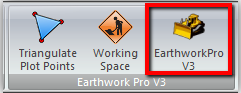
or, if your Earthworks Pro buttons are stacked...

When you click on Earthwork Pro button, Earthwork Pro V3 open a new window, and you see an orange Loading Screen...

(the window shown above is used for calculating cut and fill )
On the new window's ribbon bar there are several key Ribbon Groups:
- Zoom/Pan
- Image Tools
- Calculate
- Calculation Options
- Graphic Options
In the bottom right corner there is the “Send To PlanSwift” button. You will use this button to send the calculations back to PlanSwift after they are calculated in this window. (Figure 49)

Calculating the Topography of Existing and Proposed
Click the Calculate button from the ribbon bar. There are several options you can change before you calculate, but generally speaking you will usually calculate without changing any of the default options. (Figure 50)

After clicking the “Calculate” button, Earthworks Pro draws in a grid of Blue and Red shapes. (The default shape is the triangle and can be changed on the ribbon bar. Also, the shape’s color can be changed on the ribbon bar)

Once the topography has been calculated in this window, click the “Send to PlanSwift” button in the lower right corner to send the calculations back into the Estimating Tab of PlanSwift.
...
If you need to run calculations on the same page, we recommend you rename the folder in the Calculated Topography panel. Each time you click “Send to PlanSwift” (unless you have changed the Name of the folder) the previous calculations you sent to PlanSwift are overwritten by the latest calculations.
Changing the Name of the folder prevents the original calculations from being overwritten and adds a new folder to the Estimating Tab in PlanSwift.

It can take some time for the calculations to import into PlanSwift depending on how big the job is. PlanSwift confirms the calculations have been successfully exporting into the Estimating Tab of PlanSwift.

On the Estimating Tab in PlanSwift, select the Earthwork Pro Default layout from the left hand side and then expand the folders under the Earthwork Controls to see the calculations. (Figure 54)

The REPORTS tab also has a report to display the calculations. Use the Preview tab to see it as so. (Figure 55)

Adjusting Elevations on Multiple Contours
Earlier, we showed in the properties window that elevations can be adjusted on a digitized contour. Elevations of Proposed contours are generally the ones being adjusted, but Existing can be adjusted too. (Figure 56)

Many times, the elevations need to be adjusted on many of the Proposed elevations. Instead of changing them all one-by-one, a four step approach is suggested to adjust the elevations.
First, in the Takeoff Summary window on the left side of PlanSwift, use the lightbulbs to hide any contours you do not want to adjust. (Figure 57) Second, select the remaining contours and move them into a new folder. I labeled my new folder “Adjustments” for this example. (Figure 57) Third, click over to the Estimating Tab in PlanSwift and find those contours in the new folder you created. (Figure 58) Fourth, switch the Estimating Layout to the EWP Adjust Elevations layout, highlight all of the contours use the SHIFT key to select them, then right click in the desired column you’re are adjusting the value for and use the Fill With option to set the new value. (Figure 58)


Using Trench Tools (PlanSwift)
There are a few different trenching tools. First, you can choose to display the trench measurement by volume or by length. You can also calculate backfill by volume or by weight.
The properties window has three tabs when looking at the form view. The Trenching Home tab is where you will input the values for: Trench Width, Trench Depth, Pipe Diameter, Bedding Depth, Pipe Zone Depth, Tons per CU YD – Native Backfill, Tons per CU YD – Bedding, and Tons per CU YD – Pipe Zone Backfill. Some of these input values will be hidden or shown depending on which checkboxes are selected on this form. With all of the boxes checked you will see all the input properties. (Figure 59)

Changing the Slope Options will show you different trench slope styles in the image on this form and will also change the calculated volume of the trench automatically. After you have digitized the length of the trench, making any changes on this form will automatically recalculate the values of the connected parts.
By default the trenching tools have 5 parts attached as an assembly. Those parts are: Excavated Volume, Pipe Displaced Volume, Native Backfill, Pipe Zone Backfill, and Bedding. You can add more parts to the trenching tool from the templates, such as pipe, labor, and how many trucks needed to import or export. If you see a zero in the quantity of a part it could be a calculated value or it could be due to that part not being used, for example, not all trenches require pipe or backfill around the pipe. (Figure 60)

Using the Depth Options for a Trench
If you have a trench that has slope in it, you can use the Depth Options tab to calculate an average trench depth. You must check the box next to “Calculate Trench Depth” to see the four input properties. Enter a value for each. The trenching tool will use an average depth to then calculate the overall volume based on that average depth and the total digitized length. If your plans have trenches of multiple depths, or a single trench that will have varying depth, it is recommended that you string together several trenching tools to get the most accurate calculations. (Figure 61)

The General Instructions tab on this form contains additional text to assist you in using this tool.
Trench Reports and Layouts
The trenching tools have their own report and estimating layout. The report summarizes each of the parts in the trenching tool. The estimating layout displays the volume or weight of each part and also shows the cross sectional area of the trench. These layouts can be very useful for seeing values quickly. (Figures 62 and 63)

Adding Trench Pipe and Parts
Drag and Drop Parts for Trenches
You can drag and drop parts from the right hand Templates window onto the items on the page or onto items in the estimating tab. These parts are prebuilt, but can be customized and you can build your own folder of custom parts if you desire. (Figure 64 and 65)

The Trenching Pipe parts include a part for creating your own pipe. It is recommended that you first copy and then paste that part and then modify the copied part. This will allow you to reuse the custom part as many times as you like. Copy and Pasting parts is a very common way to customize your PlanSwift parts and enhance your Earthwork Pro plugin. (Figure 66)

Using Sectional Cut & Fill Tools
From the Templates window on the right hand side expand the folder for Sectional Cut and Fill Tools. There is single tool for Cut and a single tool for Fill. Double click or click on the green “record” button to launch these tools from the right panel in Templates. (Figure 67)

After launching the tool the properties window has an input property on the form that requires you to input a station distance. The tool is set to 25 feet by default. Enter the distance between the stations on the plans and click Ok. (Figure 68)

Use the digitizer to measure the area of the cross section for the cut or the fill. The volume is calculated by taking the cross section of the area and multiplying it by the station distance you entered for that item. You can reuse the item if the station distance is the same, but if the station distance changes, launch a new template and enter the new station distance.
(Figures 69 & 70)

To reuse the item, the green “Continue With” button on the left panel in Pages or Takeoff Summary will launch the takeoff item again with the same station distance. The station distance is automatically inserted into the name of the item for reference. (Figure 70)

Using Parts with (Enter Qty)
From the left hand panel in the Templates window open the folder and choose the part you need. These parts require you to enter a value for the quantity (as opposed to most other types of parts which have a calculated value for the quantity)
The folder for Trucks (Enter Qty) has four different parts to choose from: Import, Import (by Load), Export, and Export (by Load). These truck parts should be used to add a parts to your estimate that can be priced by CU YD or by number of loads. (Figure 71)

Note: It is important to understand that these parts will not update their values like other parts do because you are entering the quantity instead of having it calculated from the takeoff items.
Launching the EarthWork Plugin
Once all the digitizing for Existing and Proposed is complete, navigate to the Home Tab and click the Earthwork Pro V3 button from the ribbon bar...
or, if your Earthworks Pro buttons are stacked...
When you click on Earthwork Pro button, Earthwork Pro V3 open a new window, and you see an orange Loading Screen...
(the window shown above is used for calculating cut and fill )
On the new window's ribbon bar there are several key Ribbon Groups:
- Zoom/Pan
- Image Tools
- Calculate
- Calculation Options
- Graphic Options
In the bottom right corner there is the “Send To PlanSwift” button. You will use this button to send the calculations back to PlanSwift after they are calculated in this window. (Figure 49)
Calculating the Topography of Existing and Proposed
Click the Calculate button from the ribbon bar. There are several options you can change before you calculate, but generally speaking you will usually calculate without changing any of the default options. (Figure 50)
After clicking the “Calculate” button, Earthworks Pro draws in a grid of Blue and Red shapes. (The default shape is the triangle and can be changed on the ribbon bar. Also, the shape’s color can be changed on the ribbon bar)
Once the topography has been calculated in this window, click the “Send to PlanSwift” button in the lower right corner to send the calculations back into the Estimating Tab of PlanSwift.
| Note |
|---|
If you need to run calculations on the same page, we recommend you rename the folder in the Calculated Topography panel. Each time you click “Send to PlanSwift” (unless you have changed the Name of the folder) the previous calculations you sent to PlanSwift are overwritten by the latest calculations. Changing the Name of the folder prevents the original calculations from being overwritten and adds a new folder to the Estimating Tab in PlanSwift.
|
It can take some time for the calculations to import into PlanSwift depending on how big the job is. PlanSwift confirms the calculations have been successfully exporting into the Estimating Tab of PlanSwift.
On the Estimating Tab in PlanSwift, select the Earthwork Pro Default layout from the left hand side and then expand the folders under the Earthwork Controls to see the calculations. (Figure 54)
The REPORTS tab also has a report to display the calculations. Use the Preview tab to see it as so. (Figure 55)
Adjusting Elevations on Multiple Contours
Earlier, we showed in the properties window that elevations can be adjusted on a digitized contour. Elevations of Proposed contours are generally the ones being adjusted, but Existing can be adjusted too. (Figure 56)
Many times, the elevations need to be adjusted on many of the Proposed elevations. Instead of changing them all one-by-one, a four step approach is suggested to adjust the elevations.
First, in the Takeoff Summary window on the left side of PlanSwift, use the lightbulbs to hide any contours you do not want to adjust. (Figure 57) Second, select the remaining contours and move them into a new folder. I labeled my new folder “Adjustments” for this example. (Figure 57) Third, click over to the Estimating Tab in PlanSwift and find those contours in the new folder you created. (Figure 58) Fourth, switch the Estimating Layout to the EWP Adjust Elevations layout, highlight all of the contours use the SHIFT key to select them, then right click in the desired column you’re are adjusting the value for and use the Fill With option to set the new value. (Figure 58)