| Table of Contents | ||||
|---|---|---|---|---|
|
Opening Onscreen
QuoteSoft Duct Onscreen is an add-on tool to the Takeoff program much like a digitizer. In order to launch the Onscreen tool you must create a job, create a zone and enter the Takeoff screen.
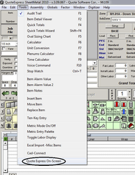
From within the Takeoff program, go to the Tools drop down menu and select QuoteSoft Duct Onscreen, at the bottom of the menu. The Onscreen window will open in its last closed location and palette configuration.
Prior to creating a zone, copy all plan files onto the Attachments tab of the current job. Please see here for instruction on copying drawings into the job and converting them if needed.
Loading a Plan File
Once Onscreen has finished loading, a navigation window will appear waiting for the selection of the plan file that is needed for this zone. Onscreen settings should be set to default to the current job’s attachment directory; if not, see here for instruction.
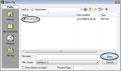
Select the plan file from within the window and click Open.
The Onscreen program will now load the plan file and perform a conversion to tiff on the PDF file. The tiff will be stored in the same attachments directory for the job.
Defining Scale
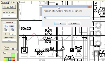
After selecting the plan file the prompt to define the scale will be shown. Onscreen does not use predetermined scales such as 1/8in, 1/4in, 1/2in, etc. In order to set the scale for the plan file simply click two points of a known length and type in the number of inches for the distance scaled. Onscreen will then build a digital scale in pixels per inch.
Once the plan file is loaded Onscreen will require the scale to be defined. An image showing three rulers will appear over your plan file. Click the green button for Define Scale.
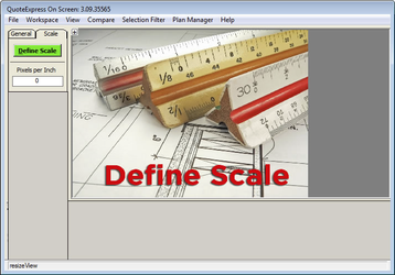
The image will be removed and the plan file will become visible.
The mouse cursor will change into a symbol indicating it is ready to define the scale.

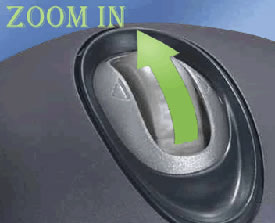
Zoom in to the print to a distance that allows a clear view of the distance that is going to be scaled to set the scale. To zoom in use the mouse wheel and roll forward, to zoom out roll the mouse wheel backwards.
To pan or move the print, right click and hold. This will grab the print and enable the ability to move the plan in any direction.
Select the longest known dimension available to set the scale. The program will have greater accuracy if the scale is set using a length that has a minimum length of 24inches.
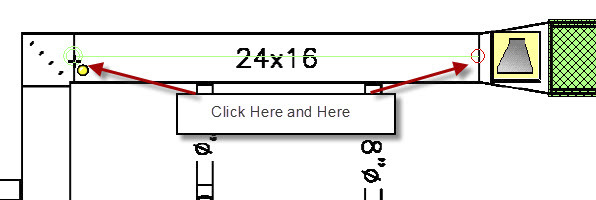
Click the left mouse button to initiate the scale set procedure, then move the mouse and click again to end the process. Using the keyboard type in the length of the scaled dimension, Onscreen will then set the scale for the print. Only one scale is allowed per drawing.
Scale Three Ways
Pairs with Multi-Fitting
Using this option will require each duct length to be placed on the plan file.


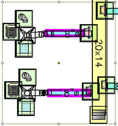
Click an item to be scaled such as Rectangular Duct, Spiral Pipe, Snaplock Pipe or Oval Pipe. Click on the plan file the beginning location of the run and then the ending point of the run.
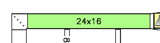
Onscreen will then draw a rectangle box over the top of the scaled item. This box will have the dimensions of the duct or pipe as entered prior to beginning the scaling process.
While in Multi-Fitting mode after selecting a fitting it is possible to continuously click the plan file and place the fitting as many times as required. Onscreen will continue to queue up another item with the same dimensions after each item is accepted.
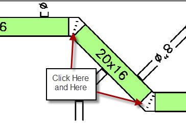
Auto-Elbow
This option will automatically insert an elbow to the proper degree based on the duct or pipe runs scaled on the plan file.

Auto-Elbow uses the configuration settings stored in the Digitizer Scale setup menu for which type of elbow to auto insert, Square or Radius. Vane selections will follow last used as the standard.
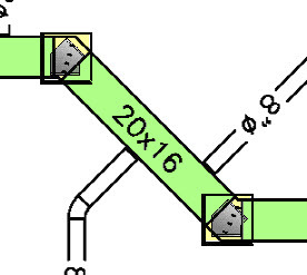
Click the beginning point for the duct run and the center of the elbow, the same as using Multi-Fitting mode. The duct run will be drawn and the elbow inserted after the second run of duct is placed. Throats will be deducted from the two duct runs as well.
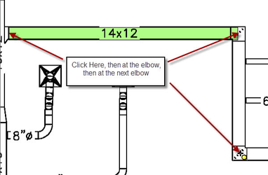
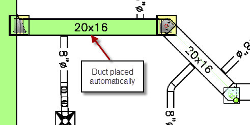
Auto-Duct
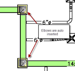
Using Auto-Duct there is no longer a need to scale duct or pipe. Placing the fitting icons will automatically give Onscreen the coordinates for the run between them. Onscreen will automatically deduct for the throats of an elbow or the length of a transition or offset.

Select the fitting that starts the duct run and place it (centered) on the plan file, this location will be used as the starting point for the duct run.
Select the next fitting in line and the scaling line will follow your mouse as you place the next fitting indicating that they are attached in Auto-Duct mode.
If an item is improperly placed or sized, click the Select button or use the Escape (ESC) key on your keyboard to exit the Auto-duct mode and either delete or edit the item that was just placed.
Assemblies & Chains
An Assembly allows the inserting of a small list of items with a single icon on the plan file. Assemblies can contain items of any type and are created to be size specific. Common uses for Assemblies include grill run-outs containing a tap, damper, flex, elbow and diffuser. Other uses are with roof top units, include the curb, economizer, unit and drops within an assembly to quickly add several items to a takeoff.
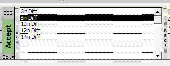
The Assembly palette, located at the bottom of the onscreen window, shows the currently available assemblies. Use the scroll bar on the side to roll down to see more of the available assemblies. The palette can be minimized and moved just the same as the rest of the palettes using the controls. For instruction, see here.
Click one of the Assemblies and place the icon on the plan file in the desired location.
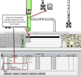
There will be one assembly icon for all the items.
However, the entire list of items is added to the Audit Trail for reporting and calculation reasons.
Deleting an assembly from a takeoff should be done from the plan file. Right Click the assembly that is to be deleted and click Delete. The items will all be removed from the Audit Trail and the Assembly icon will be removed from the plan file.
The use of Fitting Chains allows placing a group of items on the plan file with a single button click. Chains are created for Accessory items only. Common uses for the Chain shortcut are to quickly place a tap, volume damper, flex and register. Unlike Assemblies, Chains do not have to be constructed for each diameter.
For guidance on creating Fitting Chains, please see the Setup Guide and Exercise 7 for a detailed walk through diagramming the creation of Fitting Chains.
Multi-Select Options
Using the Multi-Select tool to grab several items at the same time will allow the changing of the color, sub-zone, system, etc, very quickly. The Multi-Select tool will also allow the selecting of multiple items for the purpose of a copy/paste function.
Color Change
After duct and or pipe runs have been scaled and a change in color is required, simply click the Select tool at the top of the Setup Tools bar and click and drag (left mouse button, hold down, draw a box around the items, let go of the button) this will select all items completely inside the box drawn with the click and drag motion.
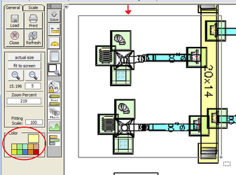
After the items are selected, click the new color on the color palette and the items will be changed.
The items that are going to be affected will be outlined with a purple line, visually allowing for confirmation that these are the items requiring the change.
Changing Sub-Zone
Just the same as the color change, draw a box around the items needing to be modified. After they are selected, simply right click on one of the items within the dotted outline box.
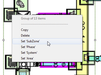
Choose the needed modification from the right click menu that is available. After the selection is made a text box will come up allowing the input of the new information. This will change the Sub-Zone, Phase, System, Area of all the highlighted items.