General Tab
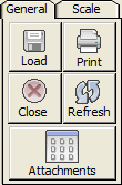
- Load – click to select a plan file to use within Onscreen.
- Print – will allow you to print either the entire plan or just a small section. You will have the option to include the plan file as well as the annotation in the print project.
- Close – click to close Onscreen.
- Refresh – if you have deleted items and their annotations or icons have not been removed from the plan file, click refresh to reload the image and the annotations.
Scale Tab
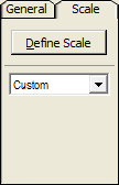
- Define Scale – this button will only appear green upon loading a plan file for the first time.
- Pixels per Inch – refers to the current scale that has been defined within this plan file.
Onscreen does not require you to select a plan scale such as 1/8, 3/16 or 1/4. By scaling two points (a diffuser, doorway, or column line, for example) on your plan file and dictating the distance between the pixels, the scale is saved and adjusted based on the zoom percentage.
Zoom Information
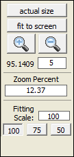
- Actual Size – will quickly zoom the view out to show you the entire plan file.
- Fit to Screen – will zoom either in or out to have the plan file fill the entire screen.
- Zoom In (+) or Out (-) buttons to move one level at a time.
- Step Size – the number in here is a percent that the Onscreen will zoom in or out when the mouse wheel is used.
- Zoom Percent – the current level of zoom.
- Fitting Scale – the current size of the fitting icons. To adjust, visit the Onscreen Options under the File drop down menu.
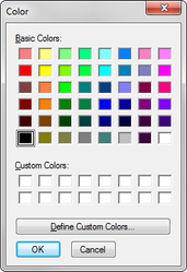
Color Palette
The large box is displaying the currently selected color. The 10 small color boxes below are definable favorites. To select a new color for the favorites buttons, right click within the box you wish to change.
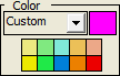
This will load a color chooser and give you a common Windows colors selector or a color mixer for your own custom colors to be created and saved.
Onscreen will default to the last used color for each item type used within the plan file. For example; if you select red with rectangular duct then change the color to green when you select round pipe, when you go back to duct the active color will return to red.
Setup Tools Bar
The Setup Tools are located under the Workspace drop down menu. These tools are the most commonly used functions and aids within the Onscreen process.
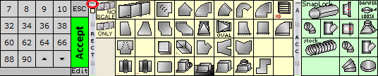
Utility Buttons

- Select – to exit scale mode, click the Select button which will return you to mouse mode. You can also hit the ESC key on your keyboard.
- Ruler tool – click and drag to scale a length without having to use a duct or pipe takeoff. This will not add an entry to your takeoff.
- Angle tool – using this tool to define a base line, you can then verify any angle on the plan file. Click two points to set the line from which to measure the angle.
- Notes – after clicking the note button, click and drag on your plan file and the note will appear in that location. You can edit the text’s font or color. Notes will be saved with the plan file until deleted.
- Zoom to Rect. Mode – click and drag a box on the plan file and the program will zoom in so that box fills the screen. This is very useful to quickly zoom into a specific location.
Takeoff Buttons
- Scale Constraining – either constrain scaling to common vertical, horizontal, and 45 degree angles, or unlock for full 360 degree scaling without constraint.


- The duct selection options allow pairs takeoff, continuous (center of fitting to center of fitting), or the Auto Elbow option. Auto Elbow will deduct the scaled duct runs for the elbows and insert the elbows automatically.


- Fitting selection offers multi-fitting drop as well as Auto Duct. Auto Duct automatically inserts the duct/pipe runs between the fitting icons.


- There are three levels to adjust for image quality: Draft, Medium, and High. Higher quality can slow the pan and scale operations.


- There are two different line styles available to you within the Onscreen program. Single Line will have a solid line (pixel width is defineable) or Double Line which will be scaled to the width of the duct or pipe.


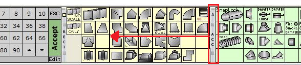
Palette Use and Configuration
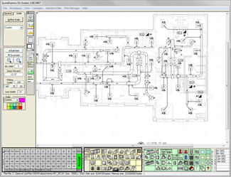
While using the Onscreen program you can use the palettes displayed at the bottom of the program to save time.
These palettes are the same as the ones located next to the Takeoff window. Using the minimize and drag to order functions of the palettes you can customize your view to help aid in your Onscreen process.
Minimizing Palettes
On each of the palettes there is a narrow title bar. This bar is located at the left of the palette it controls. The top of the bar has a dash (-) symbol which allows you to minimize the palette. Clicking this dash will “roll up” the palette leaving only the title bar. Using the minimize functions will allow you to customize the palette to either hide uncommonly used items or work within a smaller monitor area. Once the palette is minimized you can click the arrow that replaced the dash to open it back up.
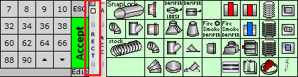
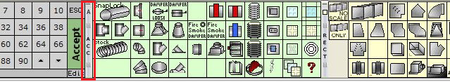
Drag to Order
The title bar also allows you to click and drag the palette to reorder your menus. With the palette open or minimized you can click (left click and hold) the title bar and drag it either right or left to reorder the palette organization.
Plan Rotation
Some plan files require a rotation due to layout or simply because of viewable preference. Rotating a plan is only recommended upon first open. Rotating a plan file once you have added fittings and duct or pipe to it can cause for misaligning of the icons and annotations.
To rotate a plan file after it has been loaded into Onscreen, go to the View drop down menu at the top of the screen and mouse over Rotate 90 Degrees to choose the direction required for rotation.
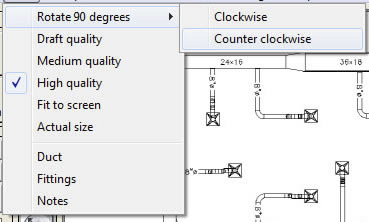
The scale that you have set will be retained after the rotation; there is no need to define the scale again.