Working with web takeoff
A takeoff is a representation of some object that you want to measure, such as a floor, wall, footing, door, or window. Takeoff items are measured by linear, area and count.
Each takeoff object includes all the information that makes the object unique, such as name, dimensions, layer, and quantity. Each takeoff item is used for specific objects on the plan, such as linear for walls and area for ceilings.
Each unique building object requires a distinct takeoff item. However, you only need to create one takeoff item for identical building objects throughout the entire plan set, regardless of type. For example, a high rise building with two different interior floor heights only requires two distinct wall takeoff items.
| You must first set the scale The most important aspect in creating successful takeoff is setting the correct scale for each plan in the document set before you begin the process of creating and drawing takeoff. It is critical that you follow the procedures for setting and verifying scale to ensure that the scale set for each plan is correct. For more information, see Setting and verifying scale. |
This section contains the following topics:
Understanding linear, area and count takeoff
Web takeoff can be linear, area and count. The takeoff you use should match the object to which it's applied, such as an area for floors or a count for fixtures.
The following table describes the three takeoffs that you can create.
| Type | Description |
| Linear | Linear takeoff applies to objects that are typically measured by linear foot, inches or meters. This includes items such as walls, foundations, curbs, piping, wiring and rafters. |
| Area | Area takeoff applies to objects that are measured by total square footage or square meters. This includes items such as slabs, ceiling tiles, flooring, roofs and facades. Also included are volume measurements for objects such as concrete slabs, poured walls and landscape fill. |
| Count | Count takeoff applies to objects best quantified as an each, such as a footing, column or fixture. |
Creating takeoff items
You can create takeoff items for linear, area and count units of measurement. Each measurement type has specific attributes. Once a takeoff item is created it can be applied as a takeoff object to a document plan.
Note: Each plan set can can only have one of the three takeoff items of linear, area and count. However, you can draw any of the takeoff items multiple times on a single sheet.
To create a new takeoff item,
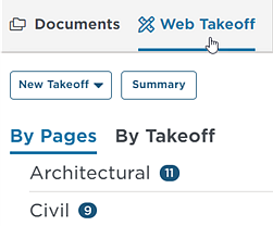
| 1 | At the top left of the window, click the Web Takeoff tab to open the takeoff application: |
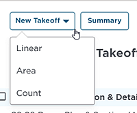
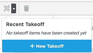
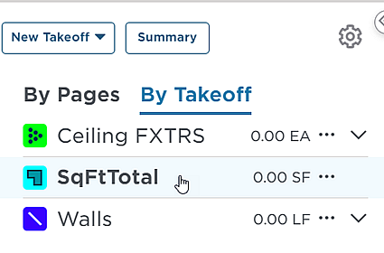
| 2 | You can access the menu to create takeoff items from the top of the document tree and from the menu bar in the viewing pane: Document tree
Viewing pane menu bar
In either location, click New Takeoff and then select the type of takeoff you want to create: Linear, Area or Count. Note: You can only create one of the three takeoff items for each plan set. However, you can apply any takeoff item multiple times on any sheet. |
| 3 | In the menu for the takeoff item, enter the properties for the item. The specific properties for each type are described in Understanding takeoff properties below. |
| 4 | Click Save when you are done. Result: The takeoff item is created. |
| 5 | To continue, see Drawing takeoff at the bottom of this section to apply your takeoff items to objects on document plans. |
Editing and deleting takeoff items
| Caution: Deleting a takeoff item deletes all takeoff objects drawn with the item on the plan set. Be sure that you want to delete the takeoff item and all associated takeoff objects before you proceed. |
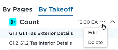
To access the edit and delete takeoff function, select where you want to edit or delete the takeoff:
- access the takeoff menu from one of the following locations:
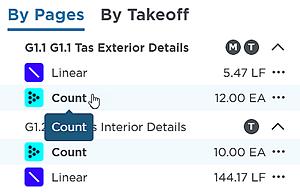
By Pages menu
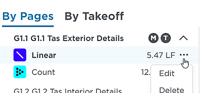
By Takeoff menu
Header menu
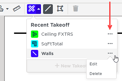
From any access location, choose from the following:
For editing,
- Click Edit and use the menu to adjust the settings. See Understanding takeoff properties in the following section for more information.
- Click Save when you are done.
For deleting,
- To delete a takeoff item,
- Click Delete and then click Continue to confirm your selection.
Understanding takeoff properties
Each takeoff type has specific properties that you set when creating the takeoff. This section describes the properties available for Linear, Area and Count takeoff items.
Linear
The following table describes the available properties for a Linear takeoff.
| Field | Description |
| Takeoff Name | Use a name that describes the physical dimensions of the object being measured. Include enough information to be clear and avoid confusion with other takeoff items. Example: 10' 4'' TYE A GWB WALL |
| Width | The dimensions of the object in feet and inches. |
| Height | |
| Color | Use color to help organize takeoff items. |
| Transparent | Selected by default, allows overlapping takeoff objects in the drawing to be visible. |
| Length | The length of the object in linear feet, inches or linear yards. |
| Surface Area (single side) | The single-side surface area in one of the following:
|
Area
The following table describes the available properties for an Area takeoff.
| Field | Description |
| Takeoff Name | Use a name that describes the physical area being measured. Include enough information to be clear and avoid confusion with other takeoff items. Example: ACT or tile flooring brick facade |
| Thickness/Depth | The thickness or depth of the object. Used to calculate volume, such as poured concrete, insulation or soil. |
| Color | Use color to help organize takeoff items. |
| Transparent | Selected by default, allows overlapping takeoff objects in the drawing to be visible. |
| Area | The total area in one of the following:
|
| Perimeter | The outside measurement in one of the following:
|
| Volume | The volume in one of the following:
|
Count
The following table describes the available properties for a Count takeoff.
| Field | Description |
| Takeoff Name | Use a name that describes the physical dimensions of the object being measured. Include enough information to be clear and avoid confusion with other takeoff items. Example: footings, columns, cornerbeads, toilets, sinks, electrical outlets. |
| Color | Use color to help organize takeoff items. |
| Transparent | Selected by default, allows overlapping takeoff objects in the drawing to be visible. |
| Shape | The shape of the object is set to Circle. |
| Visual Width | The size of the visual takeoff object when placed on the plan. |
Drawing takeoff
Once you create your takeoff items you can draw takeoff items on documents for takeoff. You can
Note: You must first create takeoff items as described in Creating takeoff items.
To draw takeoff items on a plan,
| 1 | Display the document for the takeoff in the main window. |
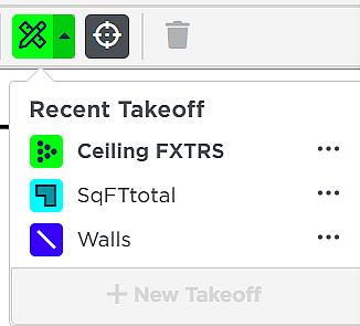
| 2 | When you select a takeoff type to use, the drawing option changes to that takeoff type. Note: Only takeoff items you have previously created are available to use. If you need to create any of the three takeoff items, see Creating takeoff items. You can select the takeoff type from three locations:
Result: Once you select a takeoff item, the drawing tool corresponding to the selected takeoff type is displayed and activated on the toolbar. Note that the takeoff item color is based on your color selection when you created the item:
Note that linear includes both the line tool and the continuous linear tool.
|
| 3 |
|
Using the takeoff task toolbar
The takeoff task toolbar at the top of the viewing pane lets work with takeoff objects added to project plans:

Tip: Hovering over an element in the toolbar displays the name and description of the tool.
Note: The takeoff icon and associated tool are dependent on the type of takeoff currently selected.
The following table describes the options on the task toolbar.
Option | Description | |
Pan tool
| Use the pan tool to move the document around in the viewing pane window. Note that the document must be maximized above 100% to activate the tool. | |
Select tool
| Use the select tool to activate takeoff objects for editing and re-positioning. This can be text boxes, lines, shapes, stamps and measurements.
Moving, resizing and deleting added elements The select tool lets you move and resize takeoff objects. Takeoff objects that are selected can be deleted using the delete tool. Note: Selected takeoff objects have handles that you can use to adjust the object to the desired shape. To move or resize an object,
To delete an object,
| |
Text annotation tools
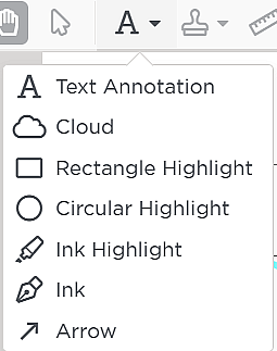
| The Text Annotation toolbar contains the elements that you can use to draw markups to project plans, as described below. | |
Text Annotation | Use to add text annotation to the document. To use the tool,
| |
| Cloud | Use to add a cloud annotation to documents. Double click on the line to complete the cloud. You can add text to a cloud by selecting the Text tool and clicking inside the completed cloud. Note that you can adjust the line width and color using the menu in the header when the cloud tool is activated. | |
Rectangle Highlight | Use to draw a rectangular highlight on the plan. Note that you can adjust the line width and color using the menu in the header when the box tool is activated. | |
| Circular Highlight | Use to draw a circular highlight on the plan. Note that you can adjust the line width and background color using the menu in the header when the disk tool is activated. | |
Ink Highlight | Use to draw free-hand highlights on the plan. Note that you can adjust the line width and color using the menu in the header when the highlighter tool is activated. | |
Ink | Use to write directly on the plan, such as with a tablet and pen. Note that you can adjust the line width and color using the menu in the header when the pen tool is activated. | |
| Arrow | Use to add arrows to documents. Note that you can adjust the line width and color using the menu in the header when the arrow tool is activated. | |
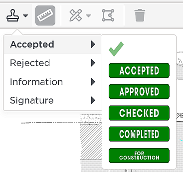
Stamp
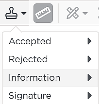
| The stamp tool lets you add standard conditions to documents. Stamps are organized into the following top categories:
Each stamp category contains subcategories that you access by clicking on the top category, as shown in the example below for Accepted:
Notes:
| |
Ruler
| The ruler tool lets you draw a measured line on the plans. Use this tool to verify known measurements when verifying document scale. | |
Delete
| Caution: Deleting a takeoff object or annotation cannot be undone. There is no undo for this action. The Delete tool is activated and turns red when an element is selected using the Select tool. Once an element is selected, click on the trash can icon to delete the element. To use the Delete tool,
Result: The element is deleted. | |
Viewing the By Pages and the By Takeoff summaries
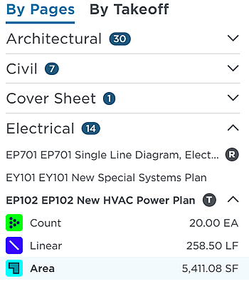
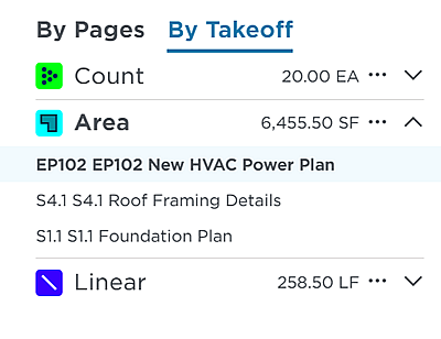
The By Pages and the By Takeoff tabs display the location and summary of takeoff, markups and revisions added to the project plans in relation to the document tree, as described in the following table.
| Location | Description |
| The By Pages tab on the left side of the window displays the location of takeoff as a summary and in relation to the entire document set. Also indicated are when documents are revisions.
|
| The By Takeoff tab on the left side of the window displays the details for the takeoff that you have added to project plans.
|
Viewing the takeoff summary
The takeoff Summary displays the name and details for each of the off items added to the plan displayed in the window.
To access the Summary menu,
- Click Summary above the document tree to open the Summary menu:
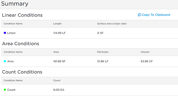
For each takeoff added to the plan, the name and details of the types are displayed in the menu.
To save the list,
- Click Copy to Clipboard.
Result: The text of the list is copied to your clipboard. You can paste the contents to a text program on your system.
© ConstructConnect All rights reserved.
