** Read this first ** This plugin requires the images to be in TIF format. Earthwork Pro cannot calculate volumes when performing takeoff on PDF pages. PDF pages must be converted to TIF images before you digitize contours or spot elevations.
Contents
Overview
The Earthwork Pro Plugin adds several tools and templates into PlanSwift.
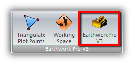
On the Home Tab you will have a new ribbon group labeled Earthwork Pro V3 with three new buttons...
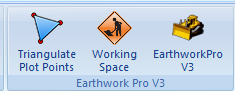
Depending on your screen size, you may see them stacked in the Earthwork Pro V3 section of the ribbon...

This guide explains how to properly use the tools and features found within the Earthwork Pro* plugin. Be sure the watch the videos to get help with how to start and finish a job. This guide is not meant to be a step-by-step “walk through” document, although it can be used as a reference for getting the work done. Primarily, it is designed to cover tools and features in more detail than in the videos.
*Version 3.0 now includes Standard and Metric Templates in one plugin.
Changes from V2:
Spot Elevations
Earthwork Pro allows you to input Spot Elevations and then triangulate the points.
Working Space
Earthwork Pro has a feature that allows you to add extra space for workers to your digitized areas. Refer to Digitizing Existing & Proposed in this guide.
What's Included
Templates
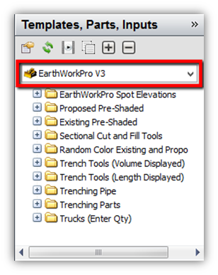
On the right hand window you will have a new set of templates as part of the dropdown menu...
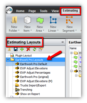
Layouts
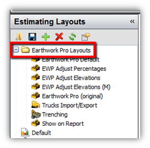
On the Estimating Tab you will have a new set of Estimating Layouts contained within a folder labeled Earthwork Pro Layouts...
Standard and Metric
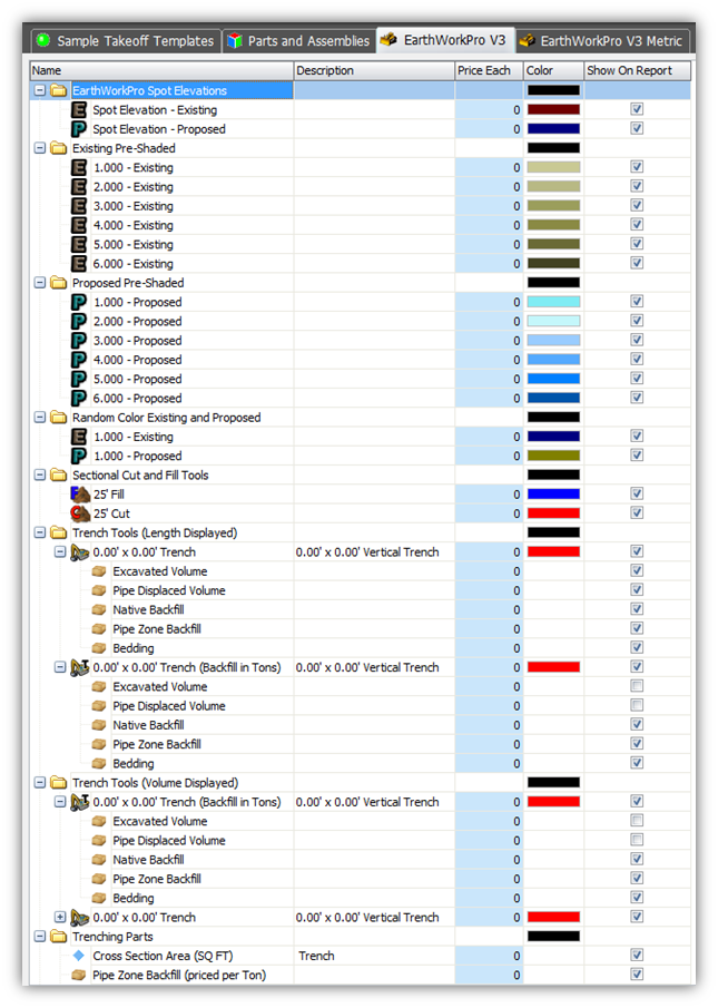
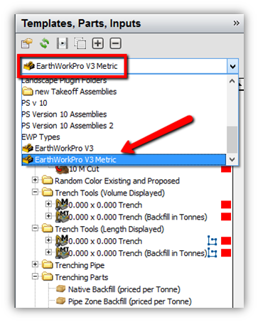
On the Templates Tab you will have two new tabs for templates. One labeled EarthWorkPro V3 and the other EarthWorkPro V3 Metric...
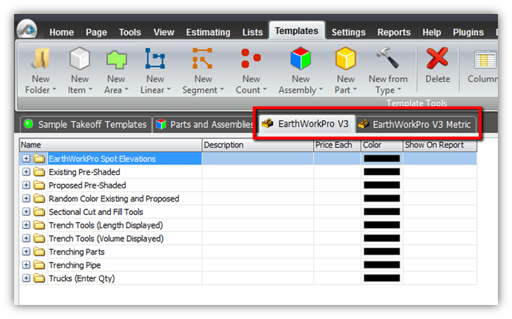
The distinction for Standard and Metric is discussed later in this article.
Reports
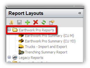
On the Reports Tab you will have a new set of Reports contained within a folder labeled Earthwork Pro Reports...
Using Earthwork Pro Plugin
Cut and Fill
You will see an orange Loading Screen when you click on Earthwork Pro V3 from the Home Tab. (Figure 7)
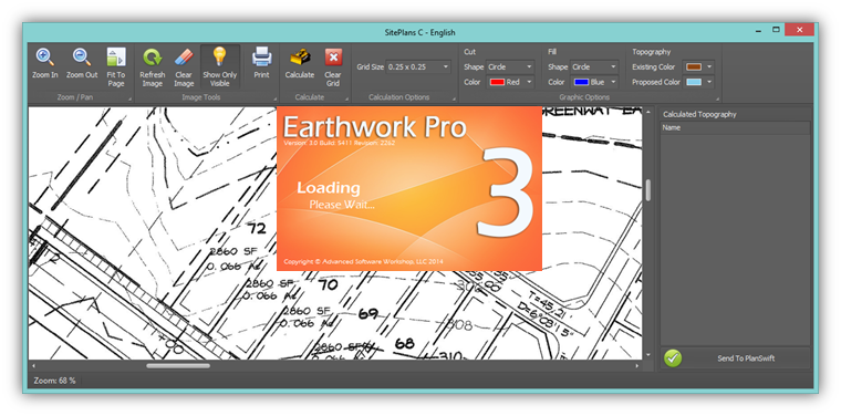
The window shown in Figure 7 is used for calculating cut and fill and will be further explained in this guide.
Trench Tools
You will have Trench Tools that can display takeoff values by Linear or Volume measurements. This is the main form you will see when you launch the Trench Tool. Trench slope options can be selected from the main form.
(Figure 8)
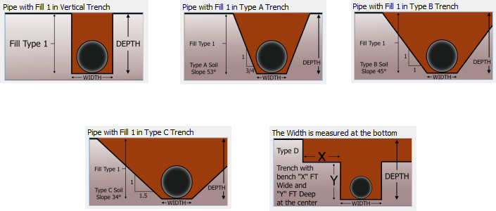
There are five total trench slope options.
Vertical Trench (Fig. 9)
Type A Trench (Fig. 10)
Type B Trench (Fig. 11)
Type C Trench (Fig. 12)
Type D Trench (trench with bench) (Fig. 13)
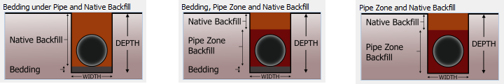
The Trench Tool also has several options for backfill. (Figures 14, 15, 16)
All of the Trench Tool features will be outlined in greater detail later on in this guide.
Sectional Cut & Fill
Sectional Cut and Fill tools are also included with this plugin and will be discussed further in this guide.
(Figure 17)
Truck Parts and more…
Truck Parts are a new addition to version 3.0. Trucks allow you to calculate Import and Export totals in either CU YD or by the load. (Figure 18)
The rest of this guide will cover all other features, parts and assemblies of Earthwork Pro V3 in more detail.
Digitizing Spot Elevations
Choosing Existing or Proposed
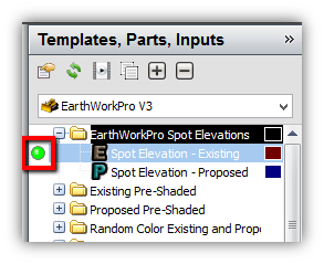
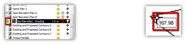
From the right hand window for Templates, you select the folder labeled EarthWorkPro Spot Elevations. In the folder you have a template for Existing and Proposed Elevations. To launch the template either double click on it or use the Green button to the left. (Figure 19)
Default Properties
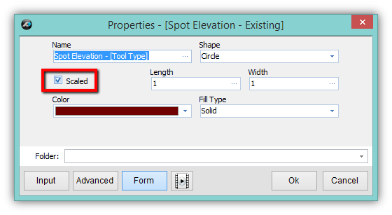
The form on the right shows the default settings. You can uncheck the box next to “Scaled” if you prefer it. Unchecking the box will make it easier to see the points you digitize on the page. (Figure 20)
Note: You can also change the properties later on after you do the digitizing.
Setting the Point and Entering the Elevation
After clicking “Ok” on the form in Figure 20 you begin by clicking any of the points on the page. After the first point is clicked you will enter the elevation and continue to the next point. Repeat the process until you have digitized all the points within the Area of Interest. (Figure 21)
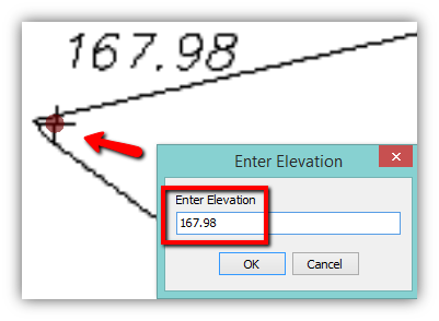
Note: Area of Interest is the area, defined by the user, which will be analyzed for Cut and Fill calculations. It is not required to digitize all of the points on a page, but just the points that will define the Area of Interest.
Triangulating the Points
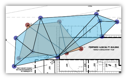
After all of the digitizing is done either for Existing Spot Elevations, Proposed Spot Elevations, or for both Existing and Proposed Spot Elevations you can click the Triangulate button on the Home Tab. PlanSwift will automatically draw areas in between all points and an average elevation is calculated from the three points it touches. Areas are shown in Blue for Proposed and Brown for Existing. (Figure 22)
Entering Elevations (mistakes)
If you made a mistake entering an elevation, and already clicked “OK” a label will show you the elevation. To change the elevation for any particular point you MUST: First, turn off the digitizer, next delete the point by Double Clicking it and finally re-digitize the point by using the green “Continue With” button found next to the item from the left hand side. (Figure 23)
Note: Changing the label will NOT change the entered elevation for the point. (Figure 24)
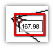
The point MUST be deleted and then re-digitized in order to enter a new elevation for it.
Digitizing Points (mistakes)
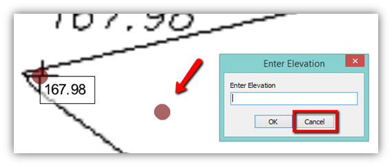
If you make a mistake and click a point where there is no spot elevation simply click the “Cancel” button on the Enter Elevation window. This will close the window and automatically delete the last point placed. To continue, proceed with clicking a new point in the correct position. (Figure 25)
Digitizing Existing & Proposed by Area
Choosing Existing or Proposed
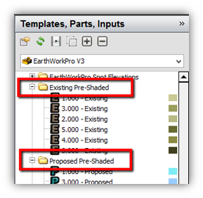
From the right hand window for Templates, you select either the folder labeled Existing Pre-Shaded or Proposed Pre-Shaded. (You can also use random colors for Existing and Proposed Contours.) There are six pre-shaded colors, brown for Existing and blue for Proposed. These templates can be re-used as many times as is necessary to complete a job. The numbers 1-6 are simply “place-holder” numbers for the pre-shaded templates. To launch the template either double click on it or use the Green button to the left. (Figure 26)
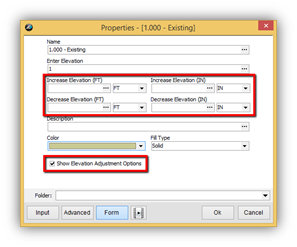
Default Properties
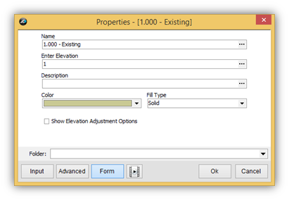
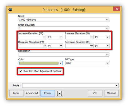
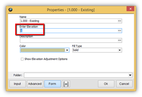
The form on the right shows the default settings. The form can also be expanded by checking the box next to Show Elevation Adjustment Options. This will add four more properties to the form that allow you to adjust the elevation that is entered. The Name property uses a formula to modify the name with the value you enter on the Enter Elevation property. You can change the Name Property, but it is not necessary or really recommended. The only thing you really need to do with this form is to enter the elevation and adjust the it if necessary. You can also add a description, but again it is optional. After entering the elevation, simply click “Ok” to begin digitizing. (Figure 27)
Note: You can always change the properties after you do the digitizing if you need to adjust the elevation later on.
Entering the Average Elevation
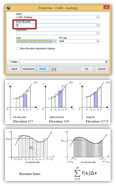
In Earthwork Pro we advise you to enter the average elevation between two contours. The most important property to understand and enter in on the form is the “Enter Elevation” property. For Existing Pre-Shaded and Proposed Pre-Shaded templates there is a number 1-6 already filled in on the property. (Figure 28) This is a simply a “placeholder value” that is designated to the pre-shaded color for that particular template. (These pre-shaded templates can be reused as many times as needed) You will highlight the “Enter Elevation” property and proceed to enter the average elevation between to two contour lines that you will be digitizing.
For example, if you have contours of 117 and 118 you will enter 117.5 for the value of the elevation between those contours. (Figure 29) The value of 117.5 will be averaged throughout the entire area that will be digitized. Hypothetically, if you were to go to the site and walk anywhere within the area between those contours of 117 and 118 you would be, plus or minus 0.5 at most, standing at an elevation of 117.5 at any given point within that area. It is very important to understand that topography lines and contours are only a very close approximation of how the earth is curved. Earthwork Pro was developed using the fundamental basic principles that are used to approximate the area under the curve in math. The area under the curve has also been sequenced using Riemann Sums and generates even better approximations with more subintervals. These basic principles are what guide us to enter the AVERAGE elevation between the two contours for the Earthwork Pro plugin.
(Figures 28, 29, 30)
Digitizing the Area Between the Contour Lines
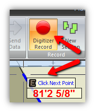
After you have entered the elevation and made any necessary adjustments, click Ok on the form. (Figure 28) The “Digitizer Record” button on the ribbon bar will light up RED indicating that the digitizer is in record mode and you will also see the Flying Tool Hint prompting you to “Click Next Point” (Figure 31)
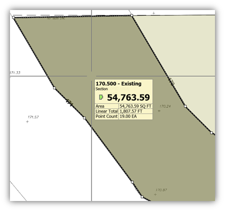
Next, you will click points following along the contour line on one side. When you reach the limit of the Area of Interest you will cross over to the other contour line and finish out defining the area between the two contour lines.
(Figure 33)
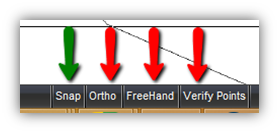
Note: You will want to turn off the ORTHO, FREEHAND, and VERIFY POINTS buttons found at the bottom of PlanSwift. You will want to use the SNAP button at times during the digitizing of all the contours. TIP: You can toggle the SNAP using the F3 key on the keyboard.
(Figure 32)
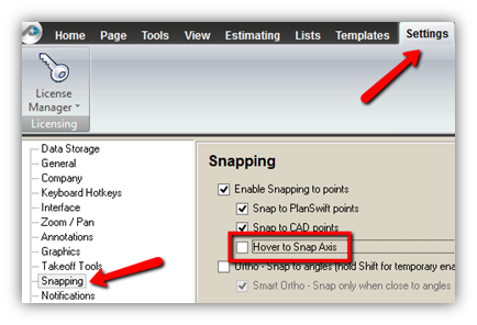
Modifying the Default Snap Settings
PlanSwift, by default, has a setting called Hover to Snap Axis which is turned on in the settings. This is used for framing and is not needed for Earthwork Pro takeoffs. You will want to turn this off in the Settings tab on the Snapping options. Simply uncheck the box next to Hover to Snap Axis. (Figure 34)
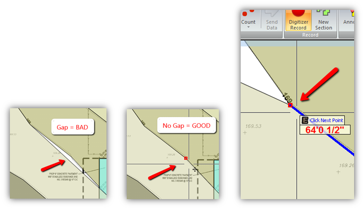
Using the Snap Feature for Digitizing
The Snap feature makes it easy to digitize along a contour line that has been previously done. You can toggle it on and off using the F3 key. You will see a RED box when you hover over a previously digitized point. This is important because you don’t want to have any gaps in the coverage of the areas you are creating for existing and proposed contours. Not only are gaps bad, but any overlapping areas are bad too. Make sure you use the Snap feature to eliminate any potential gaps or overlaps. (Figures 35, 36, 37)
Adding Points to the Area to Close the Gap
Sometimes you will realize you have a gap long after you have finished digitizing an area. (Figure 35) You can add points to the perimeter of area to easily close the gap. You add points in two main ways. You can Right Click and choose Add Point from the menu OR you can simply Double Click on the black dashed line that outlines the area. Left Clicking on the new point will make the point turn GREEN. Then move the point by Left Clicking and dragging it to where it needs to be to close the gap. (Figures 38, 39, 36)

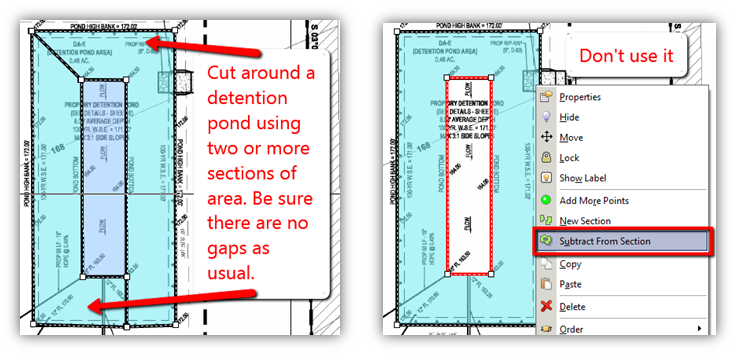
Cutting Around Topography Instead of Using Subtract From Section
PlanSwift has a feature to subtract from a section, however for the Earthwork Pro templates this feature cannot be used. It will mess up the calculations. Instead, you will need to cut around certain topography instead of cutting it out. If you used the Subtract From Section option from the right click menu you see the subtracted portion highlighted in RED. This is bad and cannot be used. DO NOT use the Subtract From Section option. If you did use it, you will need to re-digitize those areas using the cut around technique shown in the image on the left. (Figures 40, 41)
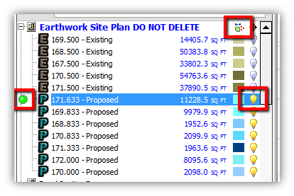
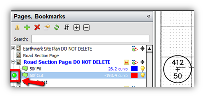
Useful Tools for Digitized Items – Hide or Show and Continue With
During the process of digitizing all of the existing and proposed contours there will be lots of items listed on the left hand side of PlanSwift in the Pages window. You can hide or show items using the YELLOW lightbulb buttons. You can also turn on or off ALL of the digitized items using the tiny toggle button to the right of the page name.
You can also use the GREEN Continue With button on the left of any item if you need to add more area for that particular contour.
(Figure 42)
Calculating Cut and Fill
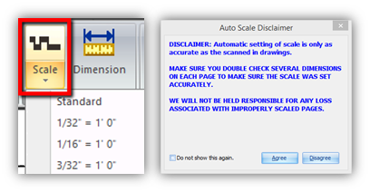
Scaling the Page
Cut and Fill cannot be properly calculated unless the page is properly scaled. Earthwork Pro requires the user to set the scale in both the X and Y axis. For most drawings you can use the drop-down auto-scale, but be sure to always verify the auto-scale by double checking dimensions.
(Figure 43)
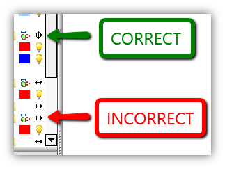
When your page is properly scaled in both the X and Y axis you will see a black arrowed icon next to the page that shows arrows both up, down, left and right. If your icon does not indicate arrows in all directions, it is incorrect and needs to be corrected before you can proceed to calculate.
(Figure 44)
Note: If you try to calculate cut and fill with the scale not being correct, PlanSwift and Earthwork Pro may not respond and you may need to close and restart them.
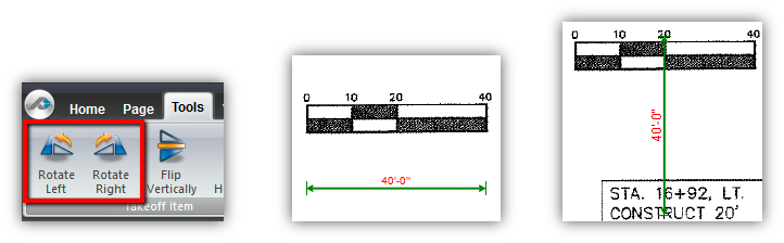
If your site plan has only one horizontal dimension to scale from you can first manually set the horizontal scale and then use the rotate tools found on the “Tools” tab to rotate the green dimension line and then scale the vertical dimension from that.
(Figures 45, 46, 47)
Note: It is possible to digitize the areas without actually scaling the page in both directions, however for calculating Cut and Fill, it is necessary that the scale is set in both the X and Y axis. Also, if you have already digitized everything and you need to redo the scale, you can. Simply click “Clear Scale” from inside the Scale window and then start over and make the scale right using the options above.
Launching Earthwork Pro V3
Once all the digitizing for Existing and Proposed is complete, click the Earthwork Pro V3 button from the ribbon bar.
(Figure 48)
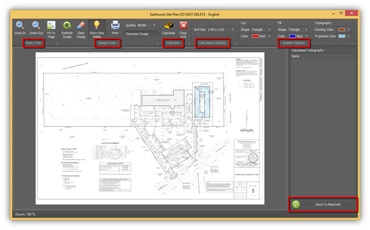
Earthwork Pro V3 will open a new window. On the ribbon bar there are several key Ribbon Groups:
- Zoom/Pan
- Image Tools
- Calculate
- Calculation Options
- Graphic Options
In the bottom right corner there is the “Send To PlanSwift” button. You will use this button to send the calculations back to PlanSwift after they are calculated in this window. (Figure 49)
Calculating the Topography of Existing and Proposed
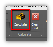
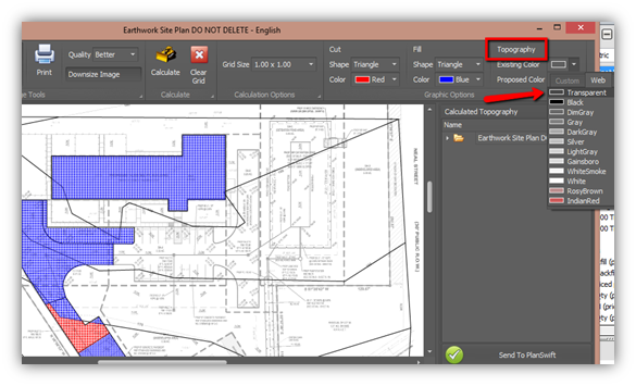
Click the Calculate button from the ribbon bar. There are several options you can change before you calculate, but generally speaking you will usually calculate without changing any of the default options. (Figure 50)
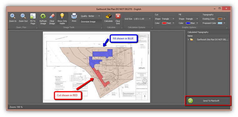
After clicking the “Calculate” button, the image will draw in a grid of Blue and Red shapes. (The default shape is the triangle and can be changed on the ribbon bar. Also, the shape’s color can be changed on the ribbon bar)
Once the topography has been calculated in this window, you can send the calculations back into the ESTIMATING tab of PlanSwift by clicking the “Send to PlanSwift” button in the lower right corner. (Figure 51)
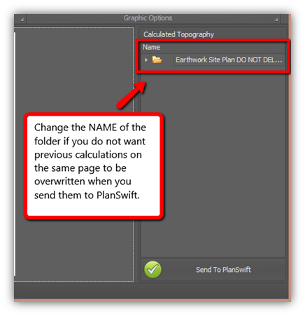
Note: For some estimators or for some projects it might be necessary to run calculations on the same page a few times. Each time you click “Send to PlanSwift” unless you have changed the Name of the folder, the previous calculations you sent to PlanSwift will be overwritten by the latest calculations. Changing the Name of the folder will make it so that the calculations are not overwritten and added to the ESTIMATING tab in PlanSwift. (Figure 52)
It can take some time for the calculations to import into PlanSwift depending on how big the job is. You will see a window that confirms the calculations have been successfully exporting into the ESTIMATING tab of PlanSwift. (Figure 53)
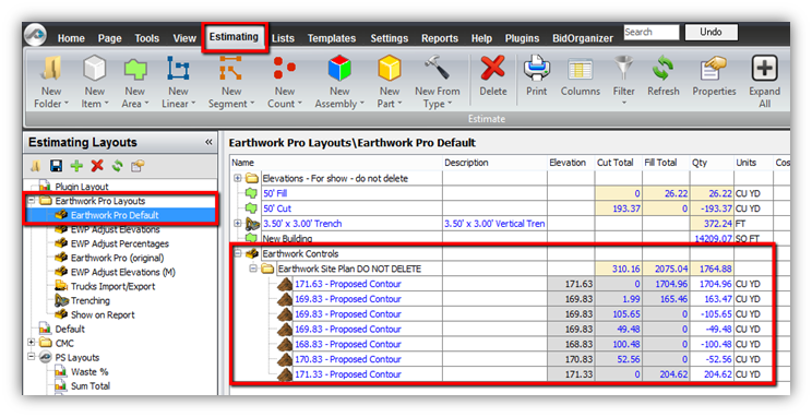
On the ESTIMATING tab in PlanSwift, select the Earthwork Pro Default layout from the left hand side and then expand the folders under the Earthwork Controls to see the calculations. (Figure 54)
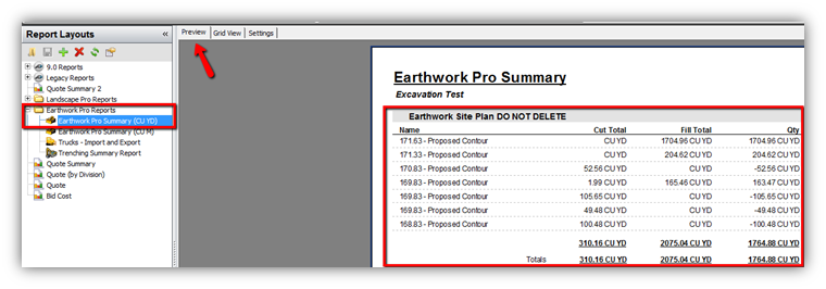
The REPORTS tab also has a report to display the calculations. Use the Preview tab to see it as so. (Figure 55)
Adjusting Elevations on Multiple Contours
Earlier, we showed in the properties window that elevations can be adjusted on a digitized contour. Elevations of Proposed contours are generally the ones being adjusted, but Existing can be adjusted too. (Figure 56)
Many times, the elevations need to be adjusted on many of the Proposed elevations. Instead of changing them all one-by-one, a four step approach is suggested to adjust the elevations.
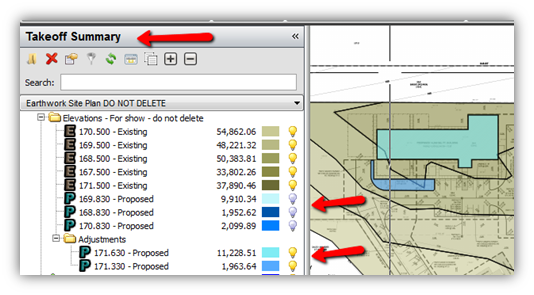
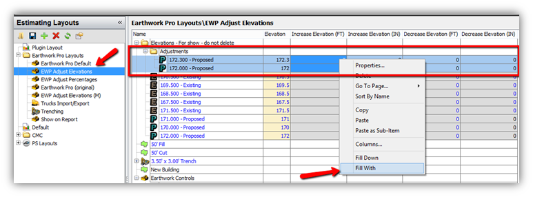
First, in the Takeoff Summary window on the left side of PlanSwift, use the lightbulbs to hide any contours you do not want to adjust. (Figure 57) Second, select the remaining contours and move them into a new folder. I labeled my new folder “Adjustments” for this example. (Figure 57) Third, click over to the ESTIMATING tab in PlanSwift and find those contours in the new folder you created. (Figure 58) Fourth, switch the Estimating Layout to the EWP Adjust Elevations layout, highlight all of the contours use the SHIFT key to select them, then right click in the desired column you’re are adjusting the value for and use the Fill With option to set the new value. (Figure 58)
Using Trench Tools
There are a few different trenching tools. First, you can choose to display the trench measurement by volume or by length. You can also calculate backfill by volume or by weight.
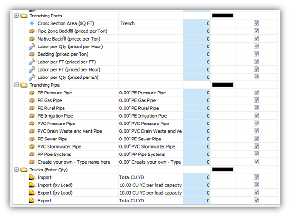
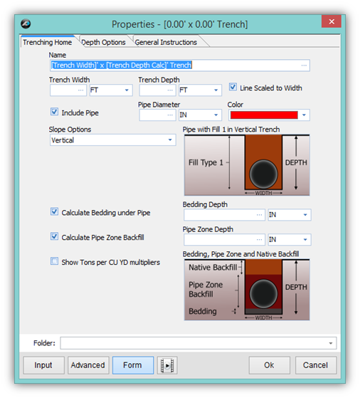
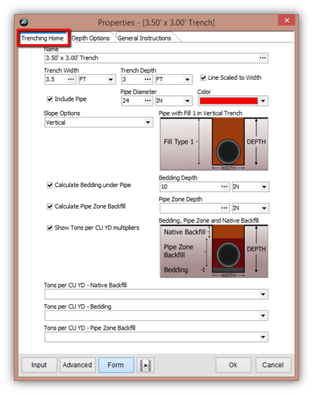
The properties window has three tabs when looking at the form view. The Trenching Home tab is where you will input the values for: Trench Width, Trench Depth, Pipe Diameter, Bedding Depth, Pipe Zone Depth, Tons per CU YD – Native Backfill, Tons per CU YD – Bedding, and Tons per CU YD – Pipe Zone Backfill. Some of these input values will be hidden or shown depending on which checkboxes are selected on this form. With all of the boxes checked you will see all the input properties. (Figure 59)
Changing the Slope Options will show you different trench slope styles in the image on this form and will also change the calculated volume of the trench automatically. After you have digitized the length of the trench, making any changes on this form will automatically recalculate the values of the connected parts.
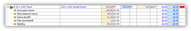
By default the trenching tools have 5 parts attached as an assembly. Those parts are: Excavated Volume, Pipe Displaced Volume, Native Backfill, Pipe Zone Backfill, and Bedding. You can add more parts to the trenching tool from the templates, such as pipe, labor, and how many trucks needed to import or export. If you see a zero in the quantity of a part it could be a calculated value or it could be due to that part not being used, for example, not all trenches require pipe or backfill around the pipe. (Figure 60)
Using the Depth Options for a Trench
If you have a trench that has slope in it, you can use the Depth Options tab to calculate an average trench depth. You must check the box next to “Calculate Trench Depth” to see the four input properties. Enter a value for each. The trenching tool will use an average depth to then calculate the overall volume based on that average depth and the total digitized length. If your plans have trenches of multiple depths, or a single trench that will have varying depth, it is recommended that you string together several trenching tools to get the most accurate calculations. (Figure 61)
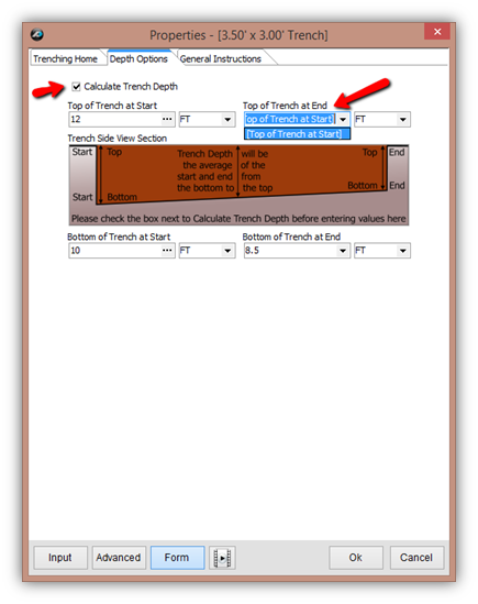
The General Instructions tab on this form contains additional text to assist you in using this tool. (Figure 61)
Trench Reports and Layouts
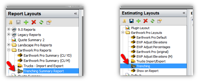
The trenching tools have their own report and estimating layout. The report summarizes each of the parts in the trenching tool. The estimating layout displays the volume or weight of each part and also shows the cross sectional area of the trench. These layouts can be very useful for seeing values quickly. (Figures 62 and 63)
Adding Trench Pipe and Parts
Drag and Drop Parts for Trenches
You can drag and drop parts from the right hand Templates window onto the items on the page or onto items in the estimating tab. These parts are prebuilt, but can be customized and you can build your own folder of custom parts if you desire. (Figure 64 and 65)
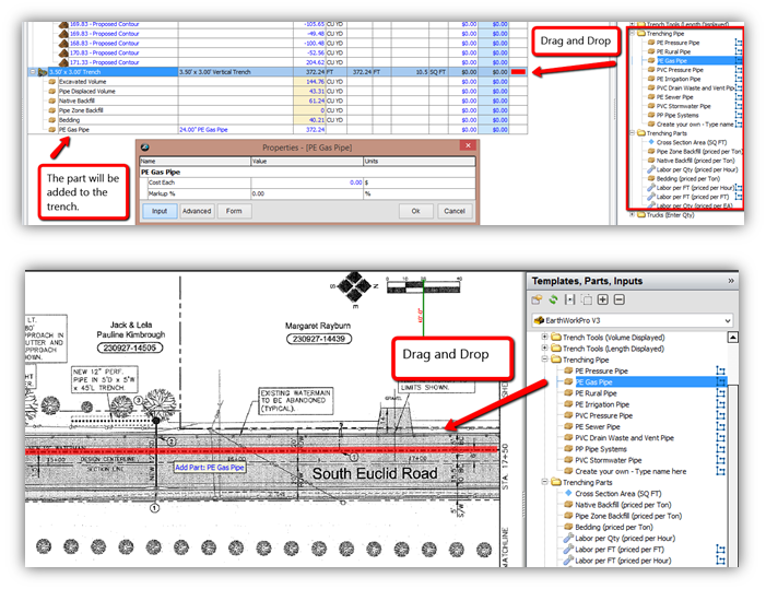
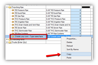
The Trenching Pipe parts include a part for creating your own pipe. It is recommended that you first copy and then paste that part and then modify the copied part. This will allow you to reuse the custom part as many times as you like. Copy and Pasting parts is a very common way to customize your PlanSwift parts and enhance your Earthwork Pro plugin. (Figure 66)
Using Sectional Cut & Fill Tools
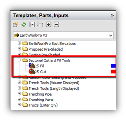
From the Templates window on the right hand side expand the folder for Sectional Cut and Fill Tools. There is single tool for Cut and a single tool for Fill. Double click or click on the green “record” button to launch these tools from the right panel in Templates. (Figure 67)
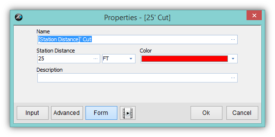
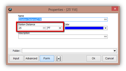
After launching the tool the properties window has an input property on the form that requires you to input a station distance. The tool is set to 25 feet by default. Enter the distance between the stations on the plans and click Ok. (Figure 68)
Use the digitizer to measure the area of the cross section for the cut or the fill. The volume is calculated by taking the cross section of the area and multiplying it by the station distance you entered for that item. You can reuse the item if the station distance is the same, but if the station distance changes, launch a new template and enter the new station distance.
(Figures 69 & 70)
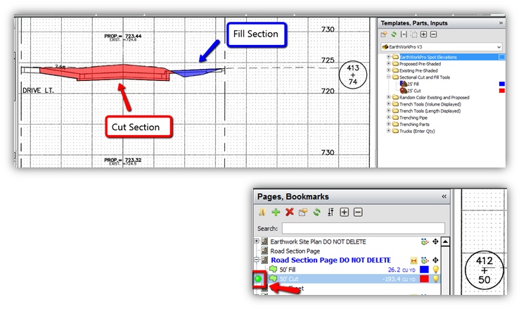
To reuse the item, the green “Continue With” button on the left panel in Pages or Takeoff Summary will launch the takeoff item again with the same station distance. The station distance is automatically inserted into the name of the item for reference. (Figure 70)
Using Parts with (Enter Qty)
From the left hand panel in the Templates window open the folder and choose the part you need. These parts require you to enter a value for the quantity (as opposed to most other types of parts which have a calculated value for the quantity)
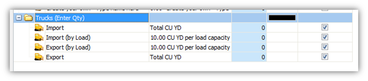
The folder for Trucks (Enter Qty) has four different parts to choose from: Import, Import (by Load), Export, and Export (by Load). These truck parts should be used to add a parts to your estimate that can be priced by CU YD or by number of loads. (Figure 71)
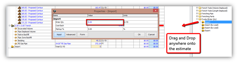
Note: It is important to understand that these parts will not update their values like other parts do because you are entering the quantity instead of having it calculated from the takeoff items.
Using Layouts and Reports
Estimating Layouts on the Estimating Tab
The Earthwork Pro plugin comes with several pre-built layouts inside of the Estimating tab. These are designed to allow you to quickly view property values in different columns on the estimate grid. The grid and its columns will change when you click on the layout. (Figure 72)
Note: For Metric users, the (M) indicates that the layout has some specific properties that use metric units instead of imperial.
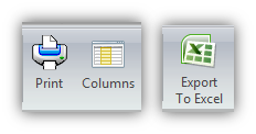
You can print any off these layouts from the estimating tab or export them to Excel.
(Figure 73)
Report Layouts on the Reports Tab
Reports are designed to function a little differently than the estimate. Reports have more filters built into them and are more printer friendly. The estimating data is what feeds information to the Reports. On the “Show on Report” estimating layout, we have built a simple way to filter the estimating data on or off of the Report. (Figure 74)
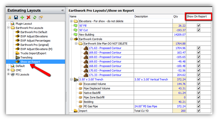
Note: This a feature we built into Earthwork Pro and is not found on other PlanSwift items by default.
The Earthwork Pro reports are designed to be used with the Preview tab, but you can also use the Grid View to view the report if you prefer. (Figure 75)
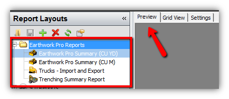
Note: Metric users should use the summary report with (CU M) to display the units in cubic meters.
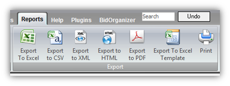
You can also export to more formats from the Reports tab and print the reports as well. (Figure 76)
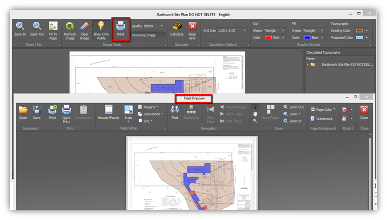
Printing the Image
When you click on the print button inside of the Earthwork Pro window, you will get a print preview window. From this window, you can print the image or export the image into a PDF or other image type. (Figure 77)
If you want to print only the red and blue areas showing the cut and fill, you can change the topography color to transparent before you click Calculate. The outline of the contours will still show up, but the color will be gone.
(Figure 78)
Choosing Standard or Metric
The templates for Earthwork Pro are divided between two tabs on the right panel in Templates. Select the tab that correlates with the unit of measure you are planning to work in. (Figure 79)
Note: If you are working on a project that has both metric and standard plans, it is strongly recommended that you break those plans into two jobs and keep the unit of measure consistent for the whole job file.
Frequently Asked Questions
Q: Will Earthwork Pro be able to do 3D models in the future?
A: Possibly, but for now there are no immediate plans to go 3D. This plugin is purposefully designed to work with the 2D plans inside of PlanSwift and to be very simplified for “quick and dirty” estimating of site work volumes.
Q: Earthwork Pro is just sitting there are not calculating anything when I click calculate, what is wrong?
A: The page scale. Earthwork Pro requires the page to be scaled in both the X and Y axis. If you forgot to scale the page both horizontally and vertically then the plugin cannot properly calculate the volume and will not respond.
Q: Do I have to digitize my existing and proposed contours on the same page?
A: YES. Earthwork Pro requires the existing and proposed contours to be on the same page to run calculations. Tip: If your existing and proposed topography is not all on the same page, you can use the OVERLAY tool to put one page on top of another as an overlay layer.
Q: If I did all my digitizing on a PDF page instead of on a TIF image, do I need to start all over?
A: YES, in most cases you will have to start over on a TIF image and redo all the work. However, sometimes the digitizing can be copied from a PDF page to a TIF image, but only if the page size of the PDF matches the image size of the TIF and the scales are the same. Copying the takeoff can work sometimes, but the user still needs to verify page size and page scale very carefully in order to still calculate accurate volumes for cut and fill.
Q: I entered a spot elevation value incorrectly. Is there a way to fix it?
A: Yes. It can be corrected in the advanced properties of the section it was counted in. See the screenshot and screencast video links:
https://www.screencast.com/t/MxtSGXdTSNeU
https://www.screencast.com/t/HmGGombbt
https://www.screencast.com/t/i5OWWOyezSn
Q: I am seeing a conversion error after I run the Triangulate Plot Points. What is wrong?
A: This is a refresh issue in PlanSwift. It can be resolved by simply clicking on the items in the Pages window or by reloading the job. You can reload the job by clicking the PlanSwift logo button in the very top left of the software and then choosing Reload Job from the menu of options. This should fix the conversion error. It happens because PlanSwift cannot always trigger all the events required to calculate everything during the triangulation process.
Links to Screencast Videos
1:03:12 - Earthwork Pro Full Length Overview
3:39 - How to Delete and Manipulate points on Triangulated Areas (generated from “Triangulate Plot Points” button)
https://www.screencast.com/t/4cMKkZ12Z0
3:58 - How to get Clear and Grub Numbers (aka Topsoil Stripping)
https://www.screencast.com/t/H1c6A5ewG
2:05 - How to properly digitize Retention Ponds or other Circular Contours
https://www.screencast.com/t/Jj4k1HT5
3:10 - How to calculate true Subgrade versus Re-spread numbers
https://www.screencast.com/t/E4xLBarwfX
4:04 - How to use Triangulated Areas with Contoured Areas – The Ultimate Solution
https://www.screencast.com/t/7KSP6fUboCJJ
2:28 - Matt’s Video: How to fix Spot Elevation Entry Errors (editing PlotPoints property on sections)
https://www.screencast.com/t/i5OWWOyezSn
4:32 - Aaron’s Video: How to fix Conversion Errors and fix Spot Elevation values (editing PlotPoints property on sections)
https://www.screencast.com/t/HmGGombbt
2:13 - Earthwork Pro Version 3.0 Highlights
Figure 42
FAQ
Question: I’ve read this user guide, and I still have questions. What do I do?
Answer: PlanSwift recommends that you purchase a training package. We highly recommend new users purchase a training package, because training is customized to each user. We offer one-on-one training and classroom training. Contact training@PlanSwift.com or at 1-888-752-6794 Ext. 4.
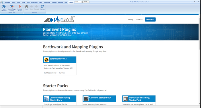
More Plugins and Starter Packs
Information on Plugins and Starter Packs is available directly on the Plugins Tab in PlanSwift...
If you encounter technical difficulty, consult this guide (including the FAQ section of this user manual) or contact the technical support department at:
PlanSwift® Technical Support support@PlanSwift.com
1-888-752-6794 ext. 2
PlanSwift also offers additional training. For training options, contact the training department at:
PlanSwift® Training Department training@PlanSwift.com
1-888-752-6794 ext. 4