Legacy Onscreen: 04. Takeoff Items
- April Friedman (Unlicensed)
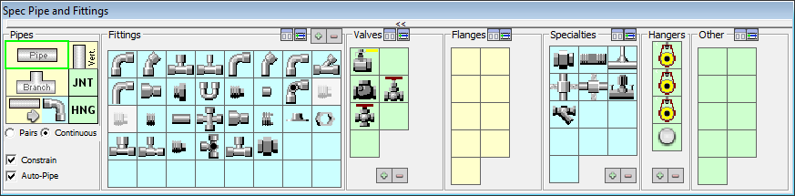
The Takeoff Items Palette is a collection of the most commonly used items. The items represented on the palette are dependent on the current spec and the active job. In this section, we will review each group of items and explain the basics for their effective use.
The Takeoff Items palette is disabled by default. To enable this palette and begin selecting items, you must first select the desired size on the Size palette.

Once you have selected a size, the Takeoff Items palette will present the items available in that sizing category.
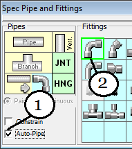
The Takeoff Items palette is organized into the following six groups:
- Pipes
- Fittings
- Valves
- Flanges
- Specialties
- Hangers
This chapter will cover each group in detail.
Pipes
There are several options available to make the process of adding pipe to your planfile a quick, easy and accurate operation. There are four available drawing modes for pipe. These modes are Standard, Vertical, Branch and Elbow. Additionally, there are four available Drawing Options that will allow you to customize the way in which your pipes are presented on the planfile.
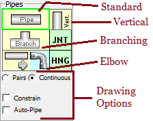
Standard Mode
To add a standard run of pipe, click on the top “Pipe” icon on the palette. When you select this drawing mode, you will see a rectangle appear around the pipe button, indicating that you have activated Standard Pipe mode.
Selecting the standard Pipe icon will set onscreen into Pipe mode. You will notice that the cursor has changed to the pipe drawing icon when you hover over the planfile.
![]()
Pipe Start Icon
![]()
Pipe Active Icon
Additionally, selecting standard pipe also enables the “Pairs/Continuous” drawing option. These two modes dictate what happens when a single run of pipe is complete.
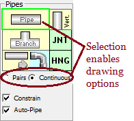
Pairs
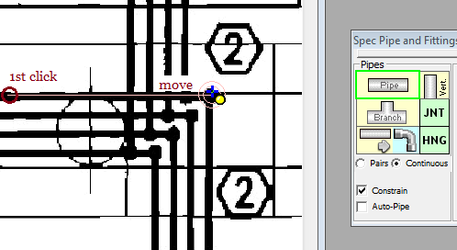
The default Drawing Mode for pipe is Pairs Mode. In this mode, use can enter a single length of pipe by clicking once on the start point and once at the end point. OnScreen will draw a pipe between the two points and calculate the length and quantity of the pipe based on the scale of your planfile. The new pipe will be shown in your Takeoff Audit Trail as soon as it has been drawn.
Continuous
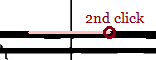
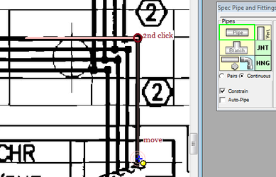
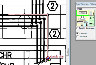
In Continuous mode, the same click that ends one run of pipe will be used as the starting point for the next run of pipe. You can continue adding pipe in this mode with each click creating a new run of pipe. When you are finished, simply Double Click to end and terminate the pipe entry mode.
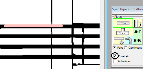
Constrain
The Constrain option when checked constrains pipe on the nearest 0°, 45° or 90° angle from the original point. When unchecked, the pipe can be placed at any angle. The following examples illustrate the difference between these modes.

Insert Between Fittings
Using the “Insert Between Fittings” mode will cause OnScreen to automatically create a run of pipe in between each fitting as they are added to the planfile.
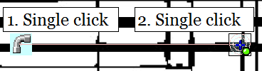
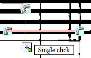
The first step to enable In-Between drawing is to select the “Insert Between Fittings” option in the Pipes group. Next, simply select any item from the Fittings, Valves, Specialties or Hangers group and move the cursor to your starting point on the planfile.
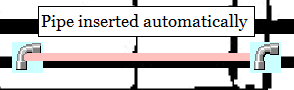
On the planfile, simply click on the points where your items should be placed…
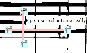
…and a new run of pipe will be drawn automatically between the new items.
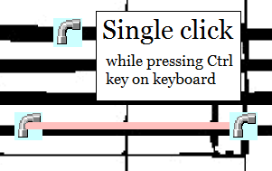
There will be times when you want to place an item without inserting a run of pipe in between. This can be accomplished by holding down the CTRL Key on your keyboard while clicking the point on your planfile where the item will be placed. This will place the item without inserting a run of pipe.
When you are ready to resume the “In Between” behavior, simply release the CTRL Key and click the planfile as before…
…and a new run of pipe will be drawn automatically between the new items.
©2022 ConstructConnect, Inc. All rights reserved.