05. Setting Up Specs
Until you become familiar with the contents of a Spec, you may want to review them to verify that they match the requirements of your job.
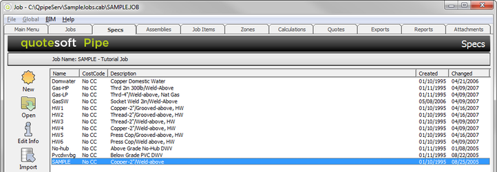
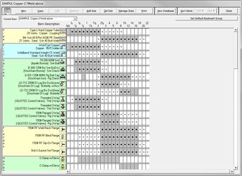
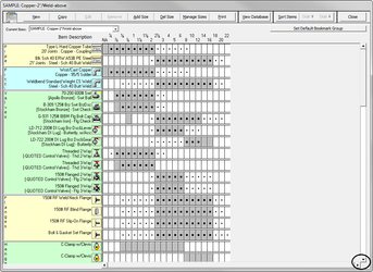
- Double click on SAMPLE Copper -2″ /Weld-above. The Spec screen appears.
NOTE: Spec screens consist of database items that define which type of pipe, fittings, valves, etc., will be used in a piping system.
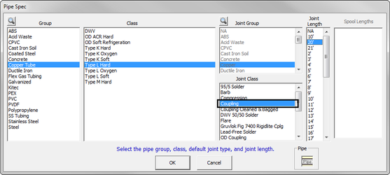
In the Spec screen, the pipe is specified as Type L Hard Copper Tube for sizes ¼”-2″. - To review this item, double click on Type L Hard Copper Tube. The Pipe Spec screen appears.
Notice that Coupling is selected for the Joint Class for copper tube rather than the type of solder. (The joint for the pipe will automatically be counted on lengths over 20 feet and a coupling will be required. The solder material for the coupling will also be included in the calculation.) - Once you have verified that the selection is correct, click to return to the Spec screen.
Fittings
Verify that the selected fittings are correct for the Specifications for our Sample Job. For this tutorial, the fittings are specified to be Wrot copper with 95/5 solder joints for sizes ¼”-2".
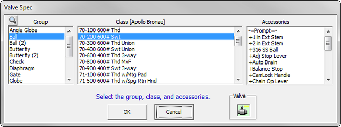
- To review this ball valve, double click on 70-200 600# Swt Ball Valve (5th row down on the Spec screen).
- A Valve Spec screen appears.
- You can now verify that the selection is correct. If any accessories are desired, they can be selected here by clicking on the accessory to highlight it. (You can select more than one accessory.)
- Click to return to the Spec screen.
To see more items on this SAMPLE Spec screen, click on the down arrow on the bottom right side of the screen. The screen scrolls so you can see more items.
Notice in the screen above, the shutoff valves for sizes 2½"-6" are specified to be Ductile Iron Lug Type Butterfly valves with Bronze Disc and Lever operator. The 8"-12" are specified to be be Ductile Iron Lug Type Butterfly valves with Bronze Disc and Gear operator.
Flanges
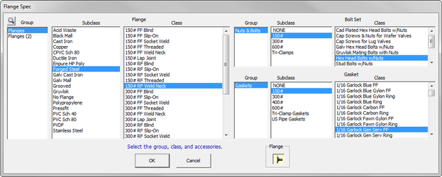
Verify that the selected flanges are correct for the Specifications. For this tutorial, the flanges are specified to be 150# Raised Face (RF) Weld Neck for sizes 2½”-16″.
- Scroll down the Spec screen until you see the flanges. Double click on 150# RF Weld Neck Flg. The Flange Spec screen appears.
- You can now verify that the selection is correct. Bolt sets and gaskets are also selected here for automatic takeoff with each flange.
- Click to return to the Spec screen.
Hangers
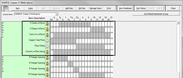
Verify that the selected hangers are correct for the Specifications. For the tutorial, the hangers are specified to be clevis type sized to the outside of the pipe insulation with a galvanized protection shield. Keep in mind you can have multiple hangers per Specification.
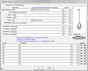
- To review this item, double click on C-Clamp w/Clevis. You can now verify that the selection is correct. All of the components shown will be calculated for each hanger of this type used in Takeoff.
Notice the circle next to Insulation Size is selected. This means the hanger is sized to include the pipe diameter plus insulation thickness (x2). If Pipe Size is selected, the hanger is sized to only pipe diameter (no insulation).
Verify that the specified insulation is correct so that the hanger size and sleeves are calculated correctly. (This is required for the proper oversizing of hangers.) - Click to return to the Spec screen.
- Scroll down to view more of the items on the Spec screen. Look at the Hanger Spacing along the left-hand column.
For this tutorial, the hangers are specified to be 5′-0″ on center for copper tube from sizes ¼”-1½” and 8′-0″ on center for sizes 2″-16″. - The first thing you want to do is delete the hangers you do not need. To do so, click on 6′ Hanger Spacing and click (at the top of the screen).
- Confirm by clicking .
- Repeat this with the 10′ Hanger Spacing.
- To change the size range for the hanger, click on the ¼” white box in the 5′ Hanger Spacing row. The box changes from white to gray. Repeat for 1¼” and 1½”.
- In the 8′ Hanger Spacing row, click and hold your mouse down on the 3″ white box and drag the cursor to the right to 16″. Release the mouse button and the sizes will be selected.
NOTE: If hanger spacing is not selected, the system cannot calculate hangers automatically.
Insulation
For the tutorial, the specified insulation is 1″ but our Spec has ½” selected.
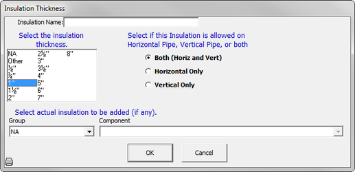
- To change this item, double click on ½” Insulation. The Insulation Thickness window appears.
- Select 1″ and click .
Notice on the screen that the 1″ insulation is specified from ¼” up to 1½” pipe diameter.
Specialties
To see Specialty items, scroll down on the Spec Screen. In specialties, you’ll see such items as Dielectric Unions, Nipples, Sleeves, and O-lets.
Saving Your Specification
- Once you are finished verifying the details for this specification, click .
- Confirm by clicking . This saves your changes and returns you to the Specs screen.
You are now ready to set up Job Items.
©2022 ConstructConnect, Inc. All rights reserved.
