09. Rectangular Pressure File
- April Friedman (Unlicensed)
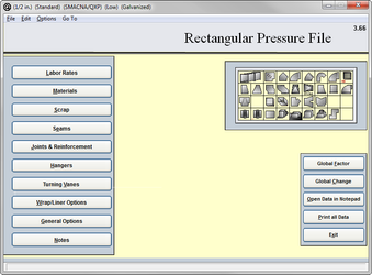
The rectangular pressure file is where you set the default material construction standards for your rectangular ductwork and fittings. It also contains the base “Item” labor for fabrication and installation and drawing (Other Labor) of the items.
The base fabrication labor includes entering the item into a plasma, burning, labeling, braking beading, cross braking, rolling, and assembly.
The base installation labor includes, loading, transporting, unloading, and placement in final location, installation to system.
The base other labor includes labor for submittals, shop drawings, O & M’s.
The information that had been input into the data file is drawn into the pressure files for you to select the data code to be used.
This data will ensure that the pressure file will be providing the correct default gauge, joint, hanger, and base item labor. information to the program in order to ensure proper automatic selection during takeoff.
Labor Rates
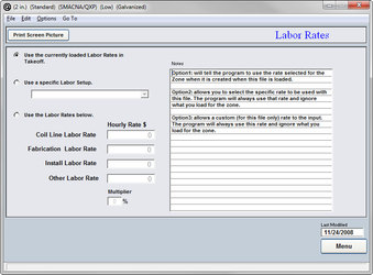
The labor rates page is for you to input the gross hourly rate. Using the currently loaded rate in takeoff allows you to specify your labor rate at the time of takeoff and not be locked into a rate. Using a specific labor setup allows you to lock the pressure file into a specific labor set up from the Data File. You can alternatively setup a custom rate for the pressure file, by entering specific rates on the labor page of the pressure file.
- Miscellaneous Labor Rate
The hourly rate that is charged for shop drawings, submittals, O & M’s and other miscellaneous paperwork. - Fabrication Labor Rate
The hourly rate applied to fabricate the materials. - Install Labor Rate
The hourly rate applied to install the materials.
Most QuoteSoft Duct contractors input their gross hourly wage. (includes wages, benefits, plus fixed overhead)
Variable overhead percentage and profit are typically added and adjusted on a per job basis in the final estimate summary.
Most QuoteSoft Duct contractors use Microsoft Excel for calculating their final estimate summary (FES) spreadsheet. See the Excel Export for more information on the FES and exporting your job data to Microsoft Excel.
Materials
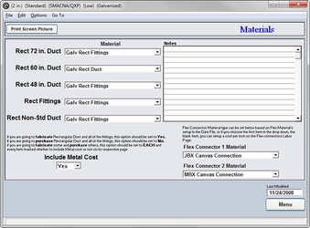
Each pressure file can be created with a different material as well as a different pressure class. In order to ensure the proper calculations the correct material must be selected for each size of standard length.
- Rect 72 in. Duct
The proper material must be chosen for 72-inch standard length. - Rect 60 in. Duct
The proper material must be chosen for 60-inch standard length. - Rect 48 in. Duct
The proper material must be chosen for 48-inch standard length. - Rect Fittings
The proper material must be chosen for all rectangular fittings. - Rect Non-Std Duct
The proper material must be chosen for all of the rectangular non-standard lengths of ducting.
Any of the materials that were created in the Central Data File can be input here.
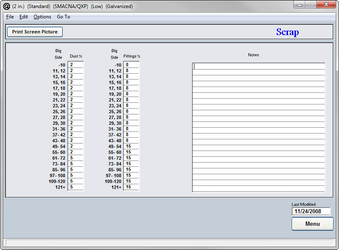
Scrap
The scrap percentages are an important part of calculating total cost of material for your duct systems. Most plasma software includes detailed reports showing historic scrap percentages over the cutting history of the table. Please refer to your cutter to determine the proper percentages for your shop.
Scrap is calculated for rectangular items by taking the total item weight with joint and seam allowances and then multiplying it but the scrap factor from the individual pressure file. The individual scrap factor used is based on the big side of the item (width or height) and if the item is straight duct or a fitting.
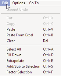
You can click on any column heading (Duct % or Fitting %) to change the entire column at once. Using the Edit menu, you can access column functions to Fill Down, Extrapolate, Add or Subtract, or Factor the selected part of a column.
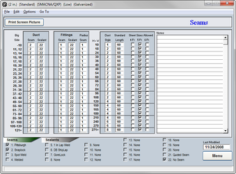
Seams
The seams that you wish to use on your rectangular duct and fittings are established in order to ensure proper labor hours and material construction. The file can be created with a single type of seam for all of the ductwork or multiple seam types can be used. Enter the default (standard) seam code you want applied for this construction standard (pressure file) This enables the specific seam for each size duct or fitting to be automatically selected and calculated during takeoff.
- Big Side
The seam to be chosen is determined by the largest dimension of the duct, the same in all of the SMACNA tables. - Duct
Seam and sealant; the specific codes from the Central Data File need to be listed here showing what seam and sealant you wish to have used on your straight duct. - Fittings
Seam and sealant; the specific codes from the Data File need to be listed here showing what seam and sealant you wish to have used on your fittings. The fittings also have a separate column for the radius seam; you can choose an alternate seam for that as well. - H + W
The height plus the width of the duct (the semi-perimeter) determines the duct style and the standard length of duct as well. - Standard Length
The standard length of your duct being manufactured in your shop should be listed; this will ensure proper calculations of ducting. - Seams/Sealants/Notes
Once you click into the either the seam or the seam sealant column the notes field then lists the data you input into the Data File to aid you in inputting the proper code. If you click into the field it will become a basic notes field for your use.
At the bottom of the page all of your seams and seam sealants are listed with check boxes next to them, these represent what you want to be listed as an alternate in takeoff. Only the items that are checked will be listed as an option.
Clicking on any of the column headings will allow you to change the entire column to one value. For example if you click on the “Duct Style” heading you will be able to change the entire column to one value. This is true for any of the columns on this page.
Using the Edit menu, you can access column functions to Fill Down, Extrapolate, Add or Subtract, or Factor the selected part of a column.
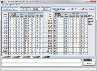
Joints & Reinforcements
Enter the default (standard) joint code you want applied for this construction standard (pressure file) This enables the specific rectangular joint for each size duct or fitting to be automatically selected and calculated on your duct, stubs and fittings, during takeoff.
The reinforcements that were established in the Data File under rods and angles are being put to use in this section. The program must be told which item code to use on what size of ducting.
- Big Side
Joint and reinforcement tables all run off of the big side of the duct, just as the SMACNA tables do. - Ga
The gauge that is to be used for a specific size and length of duct. - Joint
Select the joint that is to be used. - Rod
The code for the rod that is to be used. - # Joint Rods
The number of rods at the joint of the duct. - # Center Rods
The number of rods in the center of the duct. - Angle
The code for the angles to be used. - # Angles
The number of angles to be used.
Clicking on any of the column headings will allow you to change the entire column to one value. For example if you click on the “Gauge” heading you will be able to change the entire column to one value. This is true for any of the columns on this page.
When you click into the joint, rod or angles columns their respective codes and descriptions will be listed below with a series of check boxes next to them. The boxes that are checked will be the only options available as alternates in takeoff.
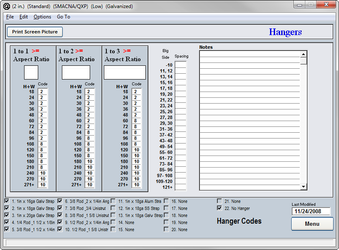
Hangers
The hanger systems that were established in the Data File are assigned to the proper semi-perimeter size of duct. Enter the default (standard) hanger code you want applied for this construction standard (pressure file) This enables the specific hanger for each size range of duct or fitting to be automatically selected and calculated on your input, during takeoff.
- Semi-Perimeter
The height plus the width of the duct. - Code
The code that was assigned to the hanger system in the Data File
When you click into the code column the hangers that are in the Data File will be listed to the right. When you click into the notes field to the right, it will clear in order for you to write notes about this particular page.
Clicking on the column heading will allow you to change the entire column to one code. Once you click on the word “Code” it will open a dialog box asking you what value to list in the entire column.
- Aspect Ratio
The aspect ratio is the relationship between the height and the width of the duct. That would be width divided by height. The aspect ratio adjustment is included so that a different hanger can be selected for both a 30 x 30 (1 to 1 ratio) duct rather than a 15 x 45 duct. (1 to 3 ratio)
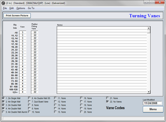
Vanes
The turning vanes that were input along with all of their data are to be used here in the pressure file to establish which vanes to use at each size of ductwork.
- Big Side
The larger dimension of the duct determines which vane is to be used. - Vane
This is the code that was established for each vane in the vane library of the Central Data File.
If you click into the vane column the vanes that were entered into the Data File will be listed to the right in the notes field. In order to get a blank notes screen again, simply click on any blank line and it will return to a notes field.
Clicking on the column heading will allow you to change the entire column to one code. Once you click on the word “Vane” it will open a dialog box asking you what value to enter in the entire column.
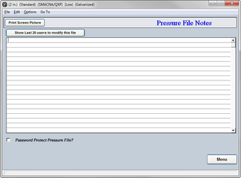
Notes
This is a miscellaneous notes field for you to use to make entries about changes that were made to the pressure file or for any other purpose.
Password protection is offered for your pressure files. Simply click the check box at the bottom of the page and type in a view and edit password of your choice.
The view password will allow you to only view the pressure file and not make any changes the values that have been entered. The edit password will give you full access to the file.
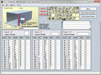
Labor
QuoteSoft Duct divides any run of ductwork into standard and non-standard lengths. For example a 13′ run of duct with 5′ standard lengths will be listed as 2 standard lengths and one 3′ non-standard length. This will ensure that the proper amount of labor hours to fabricate and install the duct has been entered.
The aspect ratio is the relationship between the height and the width of the duct. That would be width divided by height.
For example:
- 18″ x 18″ duct would be a height plus width of 36 and have an aspect ratio of 1 to 1. For every inch in width there is one inch in height.
- 24″ x 12″ duct would also be a height plus width of 36 but have an aspect ration of 2 to 1. For every one inch in height there is 2 in width or vice versa.
- 30″ x 6″ duct would also be a height plus width of 36 but have an aspect ratio of 3 to 1. For every inch in height there is 3 in width or vice versa.
If upon inspection of the labor hours already entered into the pressure file you determine that your own hours are a percentage lower or higher than those listed, you can factor the entire column either up or down a percentage. That is true for the fab, Install and the Other columns.
To factor, simply click on the heading of the column you wish to factor. For example; the fab column, click directly on the word “fab”. This will open a dialog box asking for the factor you wish to use. Type in any whole number and you will be able to drop or raise the entire column. If a 10 is used then the column will be raised by 10%. If you type in a –10 the values will then be dropped by 10%.
The same process is used for the Install and Other columns as well.
If you wish to print out the entire page in text form simply click on the “Print” button and the entire page will be viewed as a text document and ready for you to print or save on disk.
If you wish to view any other fitting or the non-standard lengths duct page simply click on the icon or button of your choice.
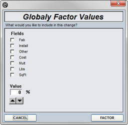
Global Factor
To globally factor the entire pressure file either up or down by a percentage, simply click on the “Factor” button from the pressure files main menu. Then select whether it is the fab, Install, Other or Cost values that you are wishing to change. It is not recommended to change all of the values at the same time because you will notice that each of the options will need to be lowered or raised a different percentage than the other.
After a choice has been made as to which values are going to be factored, you must then select a percentage. Simply use either the up or down arrows to change the percentages to the desired value.
The option of whether to include pipe should be unchecked for the most part. Generally when you are decreasing or increasing your values, you will notice that the pipe will either need to be raised or lowered by a larger percentage than that of the other fittings. Pipe should be factored separately and manually.
If there is a need to print out a text copy of the pressure file click on the “Print All Data” button from the main menu of the pressure file. Select “Yes” to confirm printing. WARNING this will print the screens and data from all pages in your pressure file. 40+ pages.
To print the data only click on the “Open Data in Notepad” button. QuoteSoft Duct will export the data to Windows Notepad program and allow you to browse the data and select the data to print.
To print an individual page click on the “Print Screen Picture” button located on each input screen.
©2022 ConstructConnect, Inc. All rights reserved.