06. Assemblies Tab
- April Friedman (Unlicensed)
Assemblies are used when you have a lot of repetition in a system; therefore, assemblies speed up your Takeoff.
Assemblies shipped from Quote Software are stored in assembly folders named HVAC and Plumbing. Assemblies are broken down by job name within these folders based on the type of equipment (e.g. Boilers, Chillers, etc.) These assemblies have graphical diagrams to assist you in selecting the correct components during the copy.
You may also wish to build your own collection of piping details. We recommend creating a personal or company-wide assembly folder with one or more jobs to store these details. You can create your own assembly; however, it may be easier to start by copying an assembly from an existing job (yellow folders) OR from the Master Folders (purple folders).
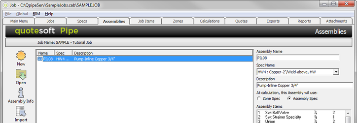
Click on the Assemblies Tab. The Assemblies screen appears.
Copying Assemblies
Click  . The Copy Assembly window appears. Copy an assembly from an existing job (yellow folders) OR from the Master Folders (purple folders). The following list of assemblies is from the HVAC Master Folder.
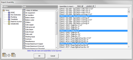
Select the folder and job from which you would like to copy an assembly. Select the desired assembly. (Multiple assemblies may be selected by holding down the control key). Note that ALL assemblies can be selected by clicking on  .
.
Creating a New Assembly
- Click
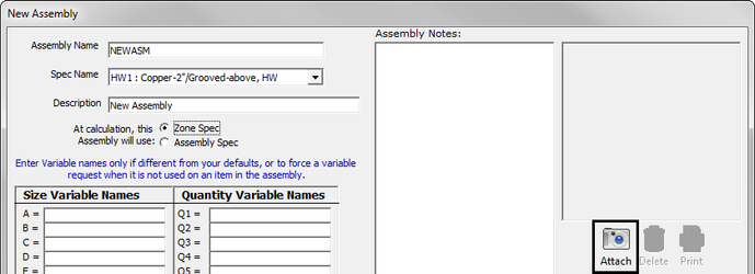
 on the Assemblies tab. The New Assembly window appears.
- Type in the information necessary.
See the next sections for details on the difference between a “Zone Spec” and “Assembly Spec” AND how to attach a picture to an assembly. - When done, click
 .
.
Editing the Assembly Information
Once you have copied (or created) all the assemblies you will need, you can edit the assembly information for this job.
- Highlight the assembly of which you want to change the information.
- Click
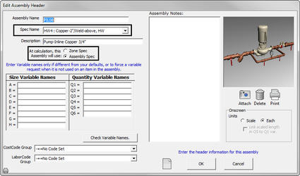
 . The “Edit Assembly Header” window appears. (It is very similar to the “New Assembly” window above.) Change the information to make it how you want it.
 - When done, click .
Difference Between an Assembly Spec and Zone Spec
When it comes time to run reports, the system looks at the specification you assigned to the assembly. This is important if, for example, you use a threaded 2″ and down in your Zone spec. The spec says that you want to use thread and couple pipe; however, in your assembly you want your hookups to your Assembly units to be copper. The Zone spec says one thing, but the Assembly spec says another. Depending on what you have selected (Zone Spec or Assembly Spec), the system uses that spec at report time.
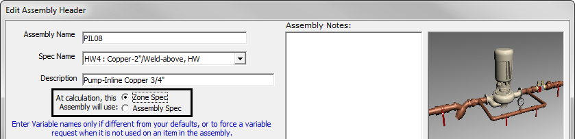
If this assembly has a specific specification you would like to use, select that Spec in the “Spec Name” field and highlight the button next to Assembly Spec.
If this assembly uses the same specifications that you assigned for the Zone, select the button next to Zone Spec.
Attaching an Image to a New Assembly
When you create new assemblies, you can import images of those assemblies. Possibly, you created these images in your CAD program. (The images can be JPEG or TIFF.) To import these images, go to the Assemblies tab.
- Click
 on the bottom right side of the Assembly screen.
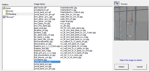
- If this is a new assembly and you have created a new image for it, select Browse to find the image on your computer. If you have an image already assigned to another assembly and you would like to use it, select if the existing image is a Base, HVAC, Plumbing, or User assembly. The list of those specific assemblies appears. Select
 to import the image.
Changing the Data in an Assembly
Once you have copied all the assemblies you need, you can add or change the data in the assembly.
Double click on the assembly you want to edit. The Takeoff screen appears for that assembly.
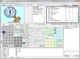
This is the "Edit Assembly" screen. You can change the items, the quantity, or size in the Assembly. Use the Assembly Takeoff List at the top right portion of the screen to see what is included in the assembly.
Variables in Assemblies
You are allowed 8 size variables (ABC) and 6 quantity Variable. By default these variables are just named A-H and Q1-Q6, however on the configuration page you may set system wide default variable names, and per assembly you may set assembly specific variable names. Please be aware that if you set a Variable name for a specific assembly, that variable will be asked for at takeoff time regardless of whether you use it in the assembly takeoff. This allows for conditions that are not tied to any item size’s or lengths.
You have a notes field for each Assembly that you can use to provide a much more in depth description and information describing the variables and how users should be setting them, these notes will be displayed to the user when they are asked to set an assemblies variables at takeoff time.
Setting Variables at Takeoff time: This screen shows notes, the new variables, a size pallette, allow scaling of length variables, and allow display of a full size image of the assembly if desired.
Pass-Through variables are allowed. For instance if you have assembly A set to ask for Length variable Q1, when assembly A is added to assembly B, instead of setting Q1 for assembly A to a value, you could set it to any of the Length variables, and it would be asked for whenever assembly B is added to a Zone.
Hanger Setup – Trapeze and Seismic
Trapeze and Seismic Hangers are not setup within the Spec but rather as an Assembly that can be placed by the user while in Onscreen Takeoff. Follow the steps below to create your own Trapeze Assembly to be used within Takeoff.
Trapeze Strut/Hangers
Create an Assembly for Unistrut Channel and Clamps by simply creating a new Assembly and taking off the required components using the appropriate variables.
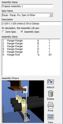
For instruction on creating a Variable Assembly please review the Variable Assembly section of this guide beginning on page 55.

Create a Zone and in takeoff select the Trapeze Assembly. This will pop up the size variable box. Enter the sizes for this trapeze and after selecting the quantity of rod hit the accept button.
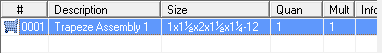
The Audit Trail shows the variable sizes:
In Onscreen, the Assembly Icon will designate the placement of the Trapeze Assemblies. The shopping cart icon will point out the position the user has placed the Assemblies.
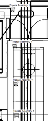
You can utilize the new measurement tool to accurately space the assemblies in Onscreen.
This tool will allow the user to space the assemblies based on spec requirements.
Trapeze Setup in Specs
Open a spec and select New. Scroll down to Hanger and select Generic from the options box. Click OK. Open the new hanger. In the first row select Unistrut > Chnl Perma-Green 12 Ga. > 1-5/8 X 1-5/8 Slotted Chnl. Set the Qty/Len to 6 and then button #2. In the second row select Hanger > Galvanized > Unistrut Cush-A-Clamp > Qty/Len is 1 and use button #1. Row three is Rod > Galv Plated All Thread Rod > Qty/Len is 8 and #1.
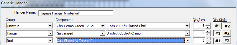
Set the Hanger spacing to 6ft. or the interval for the smallest diameter pipe for this trapeze. Note: this will give you 1 ft. of channel.
Create a Trapeze Job Item
Creating Job Items for channel lengths is quick and easy. In the Job Items tab, select New > Create Job Items using the Code box as your length.
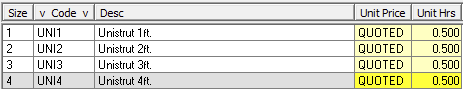
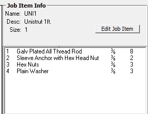
You can use the Job Item and the spec setup in combinations that work for you. Other options include adding rod, washers, nuts, and clamps to the Job Item.
Follow these exact same steps to create your own Trapeze Hanger Assemblies. Seismic Hanger Assemblies are built using the same methods, only using different parts. Please feel free to call Quote Software and schedule a training session for a more in-depth walkthrough of constructing your own Hanger Assemblies.
©2022 ConstructConnect, Inc. All rights reserved.